What Actions the ESF Relay Output Can Undertake
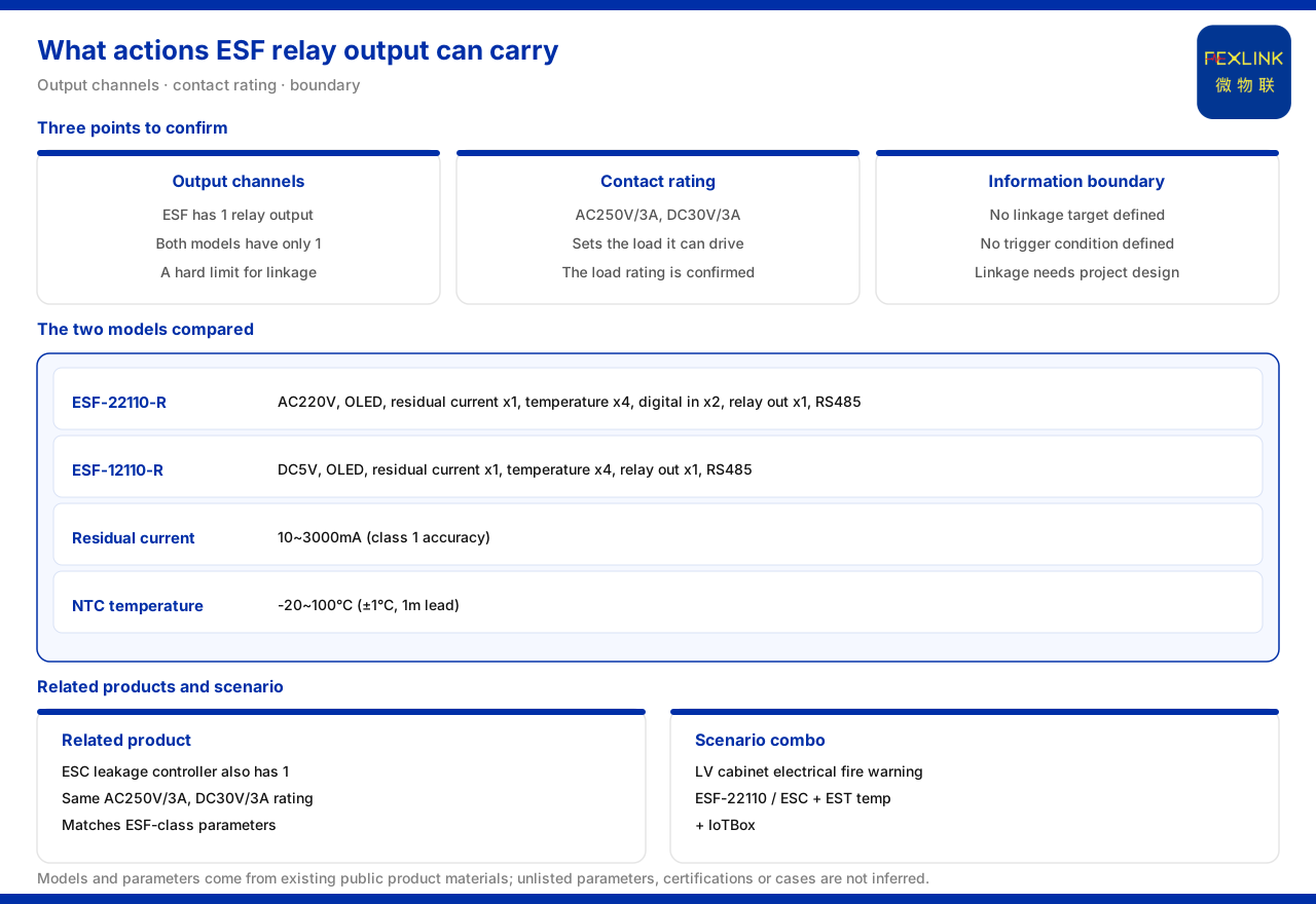
Direct answer: what can be confirmed from the material is that the relay output of the ESF electrical fire monitoring and control device is one channel, with a contact rating of AC250V/3A and DC30V/3A. The material does not define what object this output actually links to or under what conditions it operates. What can therefore be confirmed is "how large a load it can take and how many outputs there are", while "what it links to" lies outside the material's description and must be determined by project-level design. Keeping these two kinds of information apart is the precondition for using the relay output correctly.
How Many Types ESF Has and How Many Relay Outputs
The material lists two models of the ESF electrical fire monitoring and control device. The ESF-22110-R is supplied at AC220V, has an OLED display, provides one residual-current channel, four temperature channels, two digital inputs and one relay output, and communicates over RS485. The ESF-12110-R is supplied at DC5V, likewise has an OLED display, provides one residual-current channel, four temperature channels and one relay output, and communicates over RS485.
Comparing the two shows that they agree in residual-current channel count, temperature channel count, relay output channel count and communication method, differing mainly in supply method. Both the model rule and the table show that the relay output channel count of ESF is one. That is, whichever type is chosen, there is only one dry-contact output available, and this is a hard constraint when planning what to link.
Contact Rating Determines the Load That Can Be Driven
Whether the relay output can directly drive a load depends on the contact rating. The material records that the ESF relay contact rating is AC250V/3A and DC30V/3A. This means that in an AC circuit the contact can withstand a voltage of up to 250V and a current of up to 3A; in a DC circuit the voltage limit is 30V and the current limit is 3A. In engineering, the actual load should stay within these limits with a reasonable margin.
The same parameters can be seen on the ESC multi-channel leakage-current monitoring and control device: the material records that all ESC models have one relay output and that the relay contact rating is likewise AC250V/3A and DC30V/3A, consistent with ESF. This shows that within the same product family the electrical capability of the relay output is a consistent design, and selection can check the load against the same set of limits.
It should be stressed that the contact rating only states "how much voltage and current the relay can withstand"; it does not mean the output is necessarily used to drive high-power equipment. If the load exceeds the contact rating, it usually has to be switched through an intermediate relay or contactor rather than being carried directly by the controller output. This should be confirmed first in wiring design.
Residual Current and Temperature Measurement Parameters
Besides the relay output, the monitoring capability of ESF also affects its place in the system. The material records that the residual-current monitoring range of ESF is 10 to 3000mA with accuracy class 1; the temperature measurement uses an NTC with a range of -20 to 100°C, an accuracy of ±1°C and an external lead length of 1 m. These parameters show that it has both residual-current and temperature acquisition capability, and can take on early perception of electrical fire hazards in a distribution circuit.
Looking at the measurement parameters together with the relay output, the basic role of the controller can be understood: it acquires residual current and temperature and provides a usable switching action point through one relay output. Which kind of acquisition result triggers this action point and what it drives belongs to the linkage strategy, which the material does not specify.
Why the Linkage Logic Is Outside the Material's Scope
The material only lists the relay output channel count and contact rating of ESF; it does not define the specific linkage logic of the relay output, including trigger conditions and action objects. That is, the material does not state "how much residual current causes an action" or "how high a temperature causes an action", nor does it state whether the output controls a circuit breaker, an audible-visual alarm or another device. These belong to project-level design content, not to the description scope of the product material.
In engineering practice, the linkage logic usually has to be determined together with the nature of the protected circuit and the interface requirements of the fire-protection and distribution systems, and may need to be confirmed jointly with the design institute, the switchgear manufacturer and the operations party. In the scheme stage, therefore, when citing ESF it is advisable to treat "output capability" as a known condition and "linkage strategy" as a pending item.
What It Appears With in Scenarios
In the low-voltage distribution cabinet electrical fire early-warning scenario, the material recommends the combination of ESF-22110, the ESC multi-channel leakage-current device, the EST temperature device and IoTBox. This combination gives a direction: the controller and the leakage-current controller take on perception, the temperature device supplements temperature acquisition, and IoTBox takes on access. It does not state what the relay output specifically drives in this combination, so it can only serve as a configuration reference and cannot be used to infer the linkage logic backwards.
For situations needing multiple outputs or multi-channel leakage-current monitoring, attention can be paid to the ESC multi-channel leakage-current monitoring and control device; for situations needing supplementary temperature acquisition, the EST temperature device can be considered. The final form of the combination still has to be determined by the number of field circuits and the protection requirements.
Two Ways the Relay Output Is Used in Wiring
Although the material does not specify the linkage logic, two common wiring orientations can be understood from the contact rating. One is to drive a small load directly, for example an audible-visual alarm or a low-power signal circuit, in which case the load current should be clearly below 3A and the different voltage limits for AC and DC should be noted. The other is to serve as a signal contact into a higher-level system and let the latter decide the action, in which case the relay output only provides the on/off state and does not carry load power.
Neither use changes one precondition: there is only one output channel. If a site needs both an alarm and a trip action at the same time, it requires external logic or additional devices, and the same output cannot be expected to do both. This should be confirmed early in the scheme to avoid discovering insufficient interfaces at the construction stage.
The Chain from Monitoring to Output
The chain from acquisition to output can be understood as follows: residual current and temperature are the input measurement quantities, and the relay output is the output switching quantity. The controller associates the measurement quantities with the output, but the specific rules of association are defined by the project. What the material confirms is the input quantity range and the output contact capability; what it cannot confirm is the mapping relationship between the two. Seeing both ends of the chain clearly and leaving the strategy in the middle to design is a comparatively safe attitude when using this product.
Boundaries to Clarify
What the material confirms is the composition of the two ESF models; that the relay output is one channel; the contact rating of AC250V/3A and DC30V/3A; that the equivalent parameters of ESC are consistent; the residual-current and temperature parameters; and the recommended combination of the low-voltage distribution cabinet scenario. What the material does not give is the specific linkage logic, trigger threshold and action object of the relay output, nor the interface protocol with external devices. These need to be supplemented by project-level design.
Implementation Recommendations
1. First confirm that only one output is available, and plan on that basis whether it is used for an alarm, a trip or another single action. 2. Check the load against AC250V/3A and DC30V/3A, and switch through an intermediate relay or contactor when the capacity is exceeded. 3. Bring the residual current of 10 to 3000mA and the temperature of -20 to 100°C into the monitoring scheme and clarify the acquisition point positions. 4. Treat the linkage logic and trigger conditions as pending items to be confirmed jointly with the design, switchgear and operations parties. 5. When multi-channel leakage current or supplementary temperature is needed, consider the ESC and EST.
Summary
The ESF relay output supplies two things to a scheme: one switching channel and the contact rating of AC250V/3A and DC30V/3A. "How large a load it can take" can be confirmed, whereas "what it is used to link" requires project-level design. Treating output capability and linkage strategy separately avoids both over-capacity use and treating content undefined by the material as an established conclusion.