
ESF Electrical-Fire Detector
ESF Series
Adjustable leakage-current monitoring 30-1000mA and temperature detection 0-150 C, compliant with GB 14287, early warning for electrical-fire hazards.
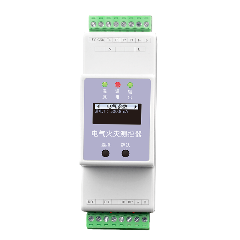
Product Overview
The ESF Electrical Fire Measurement and Control Unit uses proprietary patented software algorithm technology to accurately monitor and predict temperature and residual current in electrical systems. When residual current, temperature or other data indicators of electrical equipment become abnormal, sensors collect the indicator changes through electromagnetic induction and temperature variation effects, and transmit them to the signal processing unit. After intelligent analysis including filtering, amplification, A/D conversion, analysis, judgment and comparison, real-time data is delivered to the electrical fire monitoring system. The high-speed chip captures key parameters accurately, quickly and stably and enables early prediction, while discarding useless parameters to focus on core safety indicators.
Core Monitoring Capabilities
4-channel NTC temperature monitoring (-30~125°C, ±1°C). 1-channel residual current monitoring (10~3000mA, Class 1 accuracy). 2 digital inputs + 1 relay output with linkage control support. Non-contact split-type sensors run stably under strong electromagnetic interference. Product Features
Data Generated
Product Features
Precise Perception
The high-speed chip captures key parameters accurately, quickly and stably and enables early prediction, while discarding useless parameters such as current and voltage monitoring to focus on core safety indicators.
Enhanced Key Parameters
Non-contact split-type sensors run stably under strong electromagnetic interference, ensuring accurate and reliable monitoring data.
All-Weather Sensors
Supports 4-channel temperature and 1-channel residual current monitoring, 2 DI inputs, 1 relay output and threshold setting, allowing monitoring functions to be added quickly based on site application characteristics.
Complete Data Acquisition
Supports linkage control, standard OLED display and physical buttons for convenient on-site query and setting. RS485 communication, Modbus protocol, 36mm compact width — easy to deploy even in the tightest spaces.
Patented Algorithm Prediction
Uses proprietary patented software algorithm technology. Through intelligent analysis including filtering, amplification, A/D conversion, analysis, judgment and comparison, it accurately monitors and predicts temperature and residual current.
Compact, Flexible and Convenient
OLED display + physical buttons, pluggable terminals, 35mm DIN rail mounting, 36mm compact width — easy to deploy even in the tightest spaces. Selection Guide
System Topology
Selection Guide
Model Naming Rules
ESF - 1 2 1 1 0 - R 1 Power supply 1=DC5V / 2=AC220V 2 Display 1=LED segment / 2=OLED 3 Current channels 1=1 channel 4 Current parameter 1=10~3000mA (1A/0.5mA) 0 Reserved 0=Reserved R Communication R=RS485 (Modbus) Model Power Supply Display Residual Current Temperature Digital Input Relay Output RS485 Modbus ESF-12111-R AC 220V OLED 1 4 2 1 Supported ESF-12121-R AC 220V OLED 1 4 2 1 Supported ESF-12131-R AC 220V OLED 1 4 2 1 Supported ESF-12141-R AC 220V OLED 1 4 2 1 Supported ESF-22111-R DC 5V OLED 1 4 2 1 Supported ESF-22121-R DC 5V OLED 1 4 2 1 Supported ESF-22131-R DC 5V OLED 1 4 2 1 Supported ESF-22141-R DC 5V OLED 1 4 2 1 Supported * For other configurations, please contact sales for a customized solution. Technical Parameters
| Model | Power Supply / Display / Residual Current / Temperature / Digital Input / Relay Output / RS485 Modbus |
| ESF-12111-R | AC 220V / OLED / 1 / 4 / 2 / 1 / Supported |
| ESF-12121-R | AC 220V / OLED / 1 / 4 / 2 / 1 / Supported |
| ESF-12131-R | AC 220V / OLED / 1 / 4 / 2 / 1 / Supported |
| ESF-12141-R | AC 220V / OLED / 1 / 4 / 2 / 1 / Supported |
| ESF-22111-R | DC 5V / OLED / 1 / 4 / 2 / 1 / Supported |
| ESF-22121-R | DC 5V / OLED / 1 / 4 / 2 / 1 / Supported |
| ESF-22131-R | DC 5V / OLED / 1 / 4 / 2 / 1 / Supported |
| ESF-22141-R | DC 5V / OLED / 1 / 4 / 2 / 1 / Supported |
Technical Parameters
Basic Parameters
Operating voltage DC 4.75~5.25V (5V version) / AC 180~250V (220V version) Power consumption ≤ 2W Operating temperature -20℃ ~ 60℃ Operating humidity < 95% Weight 150g Dimensions 36 × 110 × 69mm (L×W×H) Enclosure material Thermoplastic material UL94V0 Protection rating IP20 Mounting method Standard 35mm DIN rail mounting Display OLED Communication RS485 Communication protocol Modbus protocol
| Operating voltage | DC 4.75~5.25V (5V version) / AC 180~250V (220V version) |
| Power consumption | ≤ 2W |
| Operating temperature | -20℃ ~ 60℃ |
| Operating humidity | < 95% |
| Weight | 150g |
| Dimensions | 36 × 110 × 69mm (L×W×H) |
| Enclosure material | Thermoplastic material UL94V0 |
| Protection rating | IP20 |
| Mounting method | Standard 35mm DIN rail mounting |
| Display | OLED |
| Communication | RS485 |
| Communication protocol | Modbus protocol |
Monitoring Functions
Residual current (AC) 10~3000mA, accuracy: Class 1 Temperature NTC temperature sensing: -30~125°C, accuracy ±1°C, 4 channels Digital input Dry contact input, built-in power supply, 2 channels Digital output Relay output, contact capacity AC250V/3A, DC30V/3A, normally open contact, 1 channel Linkage control Supports DI linkage control Installation Instructions
| Residual current (AC) | 10~3000mA, accuracy: Class 1 |
| Temperature | NTC temperature sensing: -30~125°C, accuracy ±1°C, 4 channels |
| Digital input | Dry contact input, built-in power supply, 2 channels |
| Digital output | Relay output, contact capacity AC250V/3A, DC30V/3A, normally open contact, 1 channel |
| Linkage control | Supports DI linkage control |
Installation Instructions
a
Installation Dimensions
36mm width 110mm height 69mm depth 35mm standard DIN rail b
Sensor Description
Sensor Specifications Residual current transformer Current ratio: 1A/0.5mA; aperture: 45mm; cable length (default): 1m NTC temperature sensor Resistance (R25°C): 10kΩ; cable length (default): 1m c
| Sensor | Specifications |
| Residual current transformer | Current ratio: 1A/0.5mA; aperture: 45mm; cable length (default): 1m |
| NTC temperature sensor | Resistance (R25°C): 10kΩ; cable length (default): 1m |
Terminal Description
Wiring definition Terminal Name Description L1 / N Power L1: live; N: neutral (220V version) 5V / GND Power 5V: positive; GND: 0V (5V version, choose either 5V or 220V) A / B RS485 communication A: RS485 A terminal; B: RS485 B terminal DI1 / DI2 Digital input Connect the other end to GND; input is directionless DO1 / DO1' Relay output Output is directionless T1 / T2 / T3 / T4 Temperature input NTC temperature input, connect the other end to GND; input is directionless I+ / I- Leakage input Leakage input positive/negative terminal Note: The 220V AC input and the 5V DC power input are mutually exclusive — do not connect both at the same time.
| Terminal | Name / Description |
| L1 / N | Power / L1: live; N: neutral (220V version) |
| 5V / GND | Power / 5V: positive; GND: 0V (5V version, choose either 5V or 220V) |
| A / B | RS485 communication / A: RS485 A terminal; B: RS485 B terminal |
| DI1 / DI2 | Digital input / Connect the other end to GND; input is directionless |
| DO1 / DO1' | Relay output / Output is directionless |
| T1 / T2 / T3 / T4 | Temperature input / NTC temperature input, connect the other end to GND; input is directionless |
| I+ / I- | Leakage input / Leakage input positive/negative terminal |
Key Points
Definition: The ESF Electrical Fire Measurement and Control Unit is a FEXLINK device dedicated to electrical fire monitoring, compliant with the GB 14287 standard, providing residual current and temperature monitoring. Core capabilities: Supports residual current and cable temperature monitoring, compliant with electrical fire monitoring system standards, with threshold alarm and RS485 upload. Application scenarios: Suitable for electrical fire monitoring scenarios such as high-rise buildings, commercial complexes, hospitals and schools. Related products: ESA electrical safety monitoring terminal, ESC multi-channel temperature measurement and control unit, SFA multi-factor measurement and control unit.
FAQ
Related Products
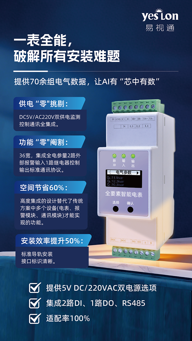
ESA Full-Factor Smart Meter
Synchronous capture of voltage, current, power, power factor and 2nd-31st harmonics, 256 samples/cycle, 0.2-class accuracy.

ESB Three-Phase Unbalance Detector
Real-time monitoring of three-phase unbalance and zero-sequence current, warning grid-unbalance risks and reducing line losses and equipment wear.

EST Temperature Detector
1-16-channel temperature monitoring, supporting NTC/PT100/thermocouple sensors, real-time sensing of distribution-node temperature.
Learn MoreESF Electrical-Fire Detector Application Scenarios
Contact us for detailed solutions, quotes and technical support.