Direct answer
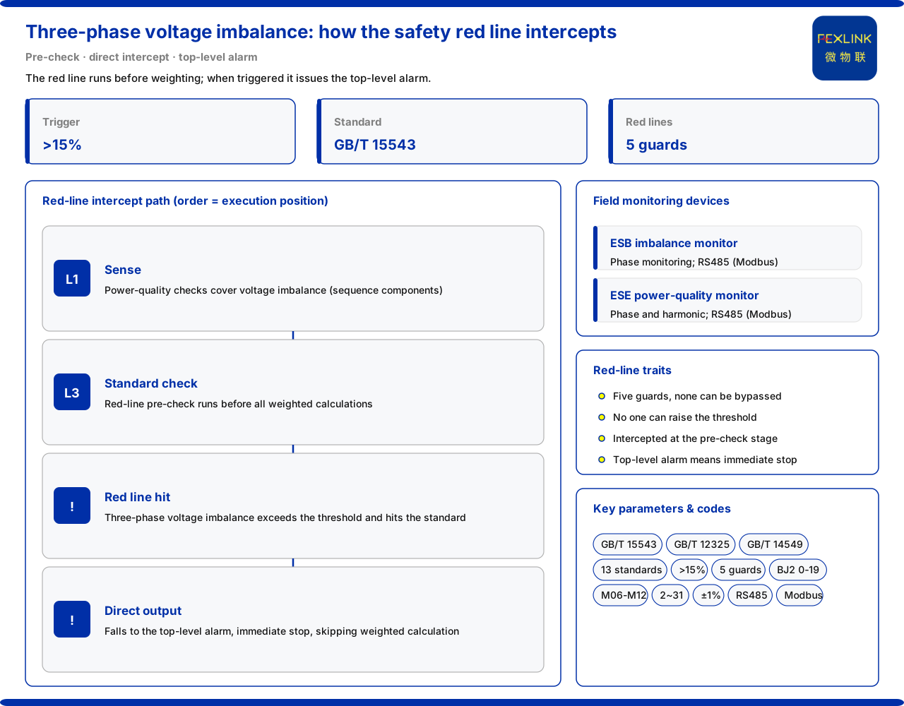
Once three-phase voltage imbalance crosses the safety red-line, the system should not continue with a "weighted average" and give a conclusion afterwards; it should intercept immediately. The product knowledge base states, in its safety red-line guard entry, that the trigger condition of the three-phase voltage imbalance safety red-line is three-phase voltage imbalance greater than 15%, based on GB/T 15543; the safety red-line guard has 5 items in total, none bypassable, and no one can raise the thresholds. The red-line executes in the front-end pre-check stage and, on triggering, directly outputs the highest alarm level and skips all weighted operations. Based on the wording listed in the product knowledge base, this article explains the red-line's meaning, execution position, alarm landing point and the field monitoring equipment used to sense three-phase imbalance; it does not infer any specific project's setting.
1. What the safety red-line guard is
The product knowledge base describes the safety red-line guard as a group of non-bypassable decision items, 5 in total, whose thresholds no one can raise. This carries two layers. First, "non-bypassable": a red-line is not a suggestion that weighting, confidence or manual confirmation can override, but a hard decision the system must execute first. Second, "thresholds cannot be raised": the threshold is fixed inside the system and cannot be relaxed by external configuration. Together, it is more like a gate — judge whether the line is crossed first; crossing leads to a definite handling path rather than later weighted calculation. The safety red-line does not depend on whether anyone notices it; it is part of the process.
A distinction is needed between "the number of guard items" and "a single red-line's threshold". The knowledge base states 5 guard items, of which the three-phase voltage imbalance red-line is one; 5 is the overall scale, 15% is this item's trigger boundary. This article discusses the latter and does not infer the other 4.
2. The red-line: above 15% and GB/T 15543
The knowledge base states that the trigger condition is "three-phase voltage imbalance greater than 15%", based on GB/T 15543. The threshold and basis form a pair: 15% is the trigger boundary, GB/T 15543 is the standard source on which it stands. The red-line converts "whether imbalance has gone out of bounds" from subjective judgement into a comparison against a fixed threshold, whose result is only "crossed" or "not crossed", avoiding different conclusions from the same data.
The technical specifications further state that the relevant engine covers 13 main standards including GB/T 12325, GB/T 14549 and GB/T 15543. GB/T 15543 is precisely this red-line's basis, showing the red-line is not an isolated empirical value but a judgement attached to the standards system; 13 is the overall coverage. This helps see "15%" as an engineering boundary with a basis.
3. Front-end pre-check
The knowledge base states that standard verification (the safety red-line front-end pre-check) executes before sub-model computation; once triggered, the system outputs the highest alarm level and skips all weighted operations. The architecture annotation likewise says the red-line intercepts directly and skips weighted operations. This timing is the key.
Without front-end execution, a system often weights and aggregates sub-model conclusions first, then looks back to judge whether an indicator is out of bounds; by then the information has been diluted or masked by high-scoring items. The front-end pre-check changes the order: judge the red-line first, intercept on crossing, and skip the weighting step, so the out-of-bounds conclusion is not flattened. The red-line's role is not a more precise score but a deterministic, undiluted conclusion.
4. The alarm landing point
The knowledge base states that on triggering, the highest alarm level is output directly; the alarm system has 6 levels, the highest being BJ2, corresponding to 0 to 19 points with immediate shutdown. After three-phase voltage imbalance goes out of bounds, the landing point is the highest tier, not a middle one. Linking "highest level" with "immediate shutdown", the handling direction is clear: no waiting for trend confirmation or manual review before escalation.
The entry gives only BJ2 as 0 to 19 points with immediate shutdown and does not expand the other 5 levels' ranges and time limits; this article states only the definite result that the trigger lands at the highest level.
5. Where imbalance is sensed
The knowledge base states that the power-quality checkup sub-models M06 to M12 cover voltage imbalance and current imbalance (sequence components), the sensing source of three-phase imbalance anomalies. Sequence components are the observation angle: both voltage and current imbalance are included in the same checkup group, so imbalance is a continuously observable quantity rather than a vague impression.
A distinction is needed between "sensing" and "judging". The checkup sub-models measure imbalance, the safety red-line judges whether it is out of bounds, and the front-end pre-check intercepts ahead of time. The three form a chain: sense, judge, intercept. Without sensing the red-line cannot trigger; without interception the result may be diluted. The entries account for each link but do not expand sampling frequency or calculation details.
6. Field equipment
The knowledge base states that field monitoring products related to three-phase imbalance include the ESB three-phase imbalance monitor (ESB-22111-R) and the ESE power-quality monitor (ESE-22111-R). The former provides phase monitoring; the latter adds harmonic monitoring to phase monitoring, covering the 2nd to 31st harmonics at ±1%. Both use RS485 (Modbus) communication and can serve as the field basis for imbalance treatment.
These two solve "whether the site can measure it"; the safety red-line solves "whether it is out of bounds and how to handle it". A traceable path is: the field monitor collects phase and imbalance data, the checkup sub-model senses, the front-end pre-check judges, and crossing leads to the highest-level alarm. The model table shows the three-phase imbalance monitor shares the architecture of the all-parameter smart meter and adds phase monitoring; this article lists it as a field basis without inferring deployment point counts.
7. Standards coverage and engineering meaning
The knowledge base states the relevant engine covers 13 main standards including GB/T 12325, GB/T 14549 and GB/T 15543. GB/T 15543 supports the imbalance red-line, GB/T 14549 relates to harmonics, and GB/T 12325 to voltage deviation; each corresponds to a different power-quality dimension. The reason the design emphasizes "front-end" and "non-bypassable" is that imbalance and harmonics are cumulative and hidden: seemingly harmless short term, they accelerate equipment ageing long term.
Three transferable points follow. First, red-line thresholds should be tied to standards, not relaxed by experience. Second, red-line judgement should precede weighted aggregation. Third, the alarm level after triggering should match the handling action: crossing means the highest level and immediate shutdown.
Scope and limitations
First, this article only restates wording listed in the product knowledge base, and its factual boundary is limited to: the safety red-line guard having 5 non-bypassable items; the three-phase voltage imbalance red-line being greater than 15%, based on GB/T 15543; the front-end pre-check preceding sub-model computation and outputting the highest alarm level while skipping weighted operations; BJ2 in the 6-level alarm system being 0 to 19 points with immediate shutdown; the power-quality checkup sub-models covering voltage and current imbalance (sequence components); the relevant engine covering 13 main standards including GB/T 12325, GB/T 14549 and GB/T 15543; and the monitoring capabilities and RS485 (Modbus) communication of the ESB three-phase imbalance monitor (ESB-22111-R) and the ESE power-quality monitor (ESE-22111-R).
Second, this article does not infer the other 4 safety red-lines' content and thresholds, nor the score ranges and time limits of the 6-level alarm system other than BJ2.
Third, 15% and GB/T 15543 are the wording listed in the product knowledge base; a specific project's setting, settings value and applicability remain subject to the latest product materials, standards and project scheme.
Fourth, this article does not constitute a commitment to any specific project's compliance conclusion or treatment effect; field equipment selection and deployment should follow the actual engineering design and approved materials.