Replacing Breakers in an Existing Distribution Cabinet: What to Verify
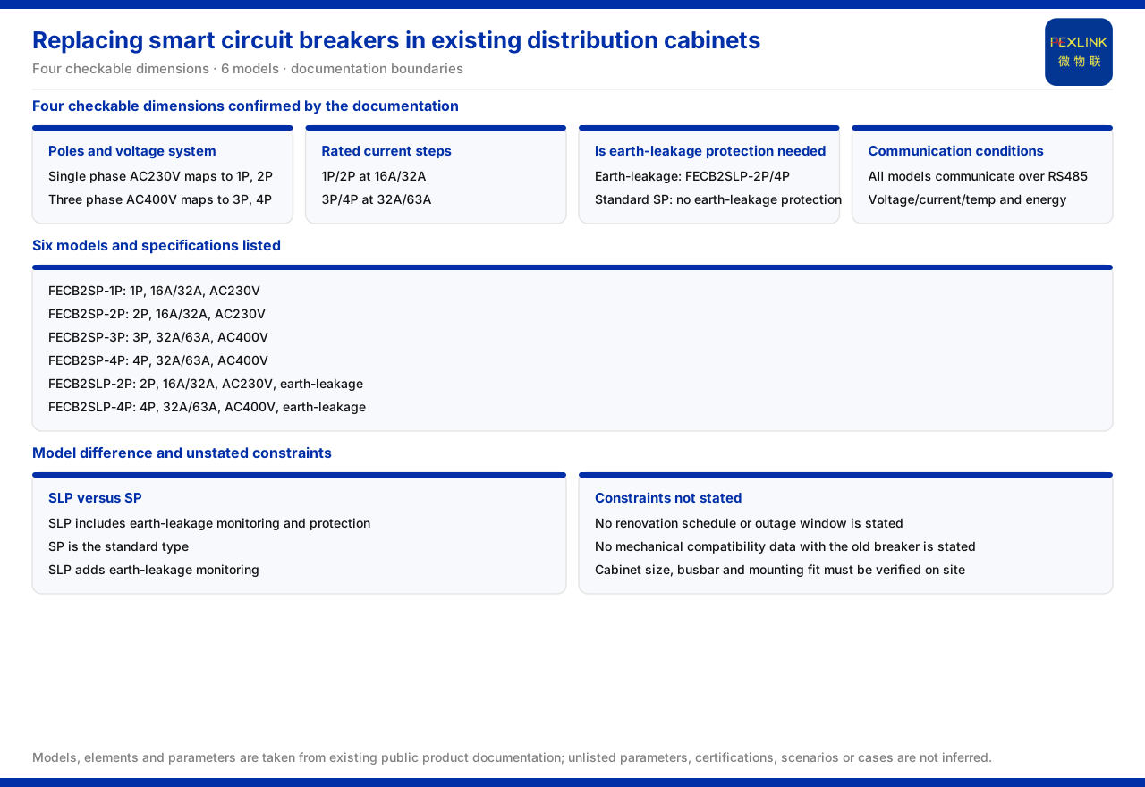
Direct answer: when a breaker in an existing distribution cabinet is replaced with an intelligent breaker, the constraints confirmable from current product documentation fall into four dimensions — whether the pole count and voltage system match, whether the rated current band covers the load, whether residual-current protection is required, and whether communication and monitoring wiring conditions exist. The listed intelligent breakers all use RS485 communication and support voltage, current, and temperature monitoring as well as energy measurement. The documentation does not state retrofit duration or outage time, nor mechanical compatibility data with the original breaker. Cabinet dimensions, busbar and installation fit, and secondary wiring space must therefore be verified on site, not inferred from the model alone.
That conclusion is conservative but is the precondition a retrofit must state first: the documentation can answer "which rating to choose," but not "will it fit, how long the power is off, or whether it matches the old part."
Why Retrofits Depend on Site Conditions More Than New Builds
A new-build project can fix the breaker specification, mounting method, and communication scheme at the design stage; the cabinet, circuits, and load are all built around that design. An existing-cabinet retrofit starts from the opposite end: it faces a cabinet already in service, an existing circuit structure, and an existing load distribution, so every replacement action has to be completed within those conditions.
What the documentation can confirm is selectability at the model level — pole count, rated current, rated voltage, whether residual-current protection is included, and the communication method. It cannot replace a judgment about mechanical and operational conditions on site. Whether the outline of the new and old breakers is the same, whether the mounting holes can be reused, and whether the busbar and conductors need modification are mechanical-fit questions the documentation does not list. The outage window and retrofit schedule are likewise not given. Once such items are written as settled facts, they can cause rework, and even safety risk, during implementation.
The correct order is therefore: map circuit requirements onto the selectable model bands from the documentation, hand mechanical and operational conditions to on-site verification, and then form a plan that both respects product facts and takes responsibility for the site.
Step 1: Match Poles and Voltage System
The standard intelligent breaker (FECB2SP) line offers four pole configurations: FECB2SP-1P and FECB2SP-2P are rated AC230V, while FECB2SP-3P and FECB2SP-4P are rated AC400V.
The voltage system of a circuit in an existing cabinet directly determines the selectable pole count: a single-phase circuit corresponds to 1P or 2P, and a three-phase circuit to 3P or 4P. When checking, first see whether the original circuit is single-phase or three-phase and whether the incoming line is a phase conductor or a phase and neutral conductor, then check whether the bus voltage level is AC230V or AC400V, and only then decide which pole count can be used. If either the pole count or the voltage system does not match, the plan has to be adjusted rather than handled on the assumption that "a large enough current rating will do."
This correspondence is the backbone of selection: fix poles and voltage first, then current bands, and only then protection and communication. Reverse the order and it becomes easy to choose a residual-current model whose pole count is inapplicable, or a suitable pole count that cannot cover the load.
Step 2: Cover the Actual Load With the Right Current Rating
The standard intelligent breaker (FECB2SP) offers two rated-current bands: 1P and 2P are 16A/32A, while 3P and 4P are 32A/63A. The selectable current band therefore differs with the pole count. During selection, the actual load current of the circuit should fall into the corresponding band; the nominal value of the old breaker should not simply be copied.
In a retrofit, the circuit load may already have changed: some circuits have gained load, and some are operated at reduced capacity. If the old nominal current is carried over without reviewing the actual load, the band may end up too high or too low. The correct approach is to confirm the voltage system and pole count first, then choose the band that covers the load within those available for that pole count; when the old specification does not match, the documented bands should be used to re-match.
Step 3: Decide Whether RCD Protection Is Needed
Intelligent breakers come in a standard model and a residual-current model. The standard model is identified by SP and the residual-current model by SLP. In addition to leakage monitoring, the residual-current model provides residual-current protection and suits circuits that require it.
The intelligent breaker with residual-current protection (FECB2SLP) is available in 2P and 4P: FECB2SLP-2P is 2P, 16A/32A, AC230V; FECB2SLP-4P is 4P, 32A/63A, AC400V. The pole count, current bands, and voltage system of the residual-current model follow the same banding logic as the standard model at the same pole count; the difference is whether residual-current protection is integrated.
Whether to use the residual-current model therefore depends on the circuit's requirement for residual-current protection, not on the pole count itself. Facing the same 2P or 4P circuit, either model may be chosen. During a retrofit, first establish whether the circuit needs residual-current protection, then choose the model at the corresponding pole count. Note that the documentation only states that the residual-current model "provides residual-current protection and includes leakage monitoring," without expanding on operating characteristics or setting methods; those details depend on site requirements and later documentation.
Step 4: Confirm Communication and Monitoring Wiring
All six intelligent breakers use RS485 communication and support voltage, current, and temperature monitoring as well as energy measurement. For a retrofit this raises two existing conditions: whether the cabinet has an RS485 wiring path, and which system level these monitoring data feed into.
If the original cabinet has no reserved communication line or acquisition channel, the scope extends beyond replacing the breaker body: RS485 cabling, the mounting location of an acquisition terminal or gateway, and the path for data to reach the next level all have to be planned together. Conversely, if usable communication and acquisition conditions already exist, the focus is how new circuits merge into the existing link, how addresses are assigned, and how wiring is routed. In either case, communication and monitoring capability is an explicit documentation attribute that can be used as a basis for the plan; the specific installation workload and outage arrangement remain site matters.
Constraints the Documentation Does Not State
It should be emphasized that the documentation gives only the pole count, rated current, rated voltage, residual-current option, and communication attributes of the intelligent breakers. It does not state the duration of a retrofit, the outage time, or mechanical compatibility data with the original breaker. Whether the outline dimensions and mounting holes of the new and old breakers are identical, whether the busbar and conductors can be reconnected directly, whether the cabinet layout needs adjustment, and how long the outage window and overall retrofit take therefore cannot be asserted from experience in a plan.
These are on-site verification items. They look like construction details, yet they directly determine whether a retrofit can be completed in one pass, whether extra outage time is needed, and whether there is a rework risk of being unable to reassemble after replacement. Any unverified compatibility conclusion can push risk from the design stage to the implementation stage.
A Pre-Commissioning Checklist
To keep a retrofit plan both within product facts and executable, the following checks are recommended before the plan is finalized:
1. Record the pole count, voltage system, and load of each original circuit and compare them with the documentation. 2. Establish which circuits require residual-current protection, decide between the models, and lock the pole count and current band. 3. Check the RS485 cabling, acquisition terminal or gateway location, and uplink path. 4. Measure installation space, conductor directions, and operating clearances on site, and write the mechanical conclusions into the plan. 5. Combine the outage arrangement and work windows to set the implementation sequence; do not cite duration data absent from the documentation.
Summary
For replacing a breaker in an existing distribution cabinet, the judgment the documentation supports is: select the corresponding standard or residual-current model by pole count, voltage system, rated current band, and protection requirement; all six use RS485 communication and support voltage, current, and temperature monitoring as well as energy measurement. The judgment it does not support is mechanical compatibility, duration, and outage time.
Separating the confirmable from the to-be-verified is the baseline that makes a retrofit plan valid. For engineers, the safest practice is to select the model band correctly from the documentation first, then complete the mechanical and operational conditions through on-site measurement. For review and delivery, it is to check that unlisted compatibility or duration is not stated as settled conclusion — allowing an actionable recommendation without overstating product facts.