Direct answer
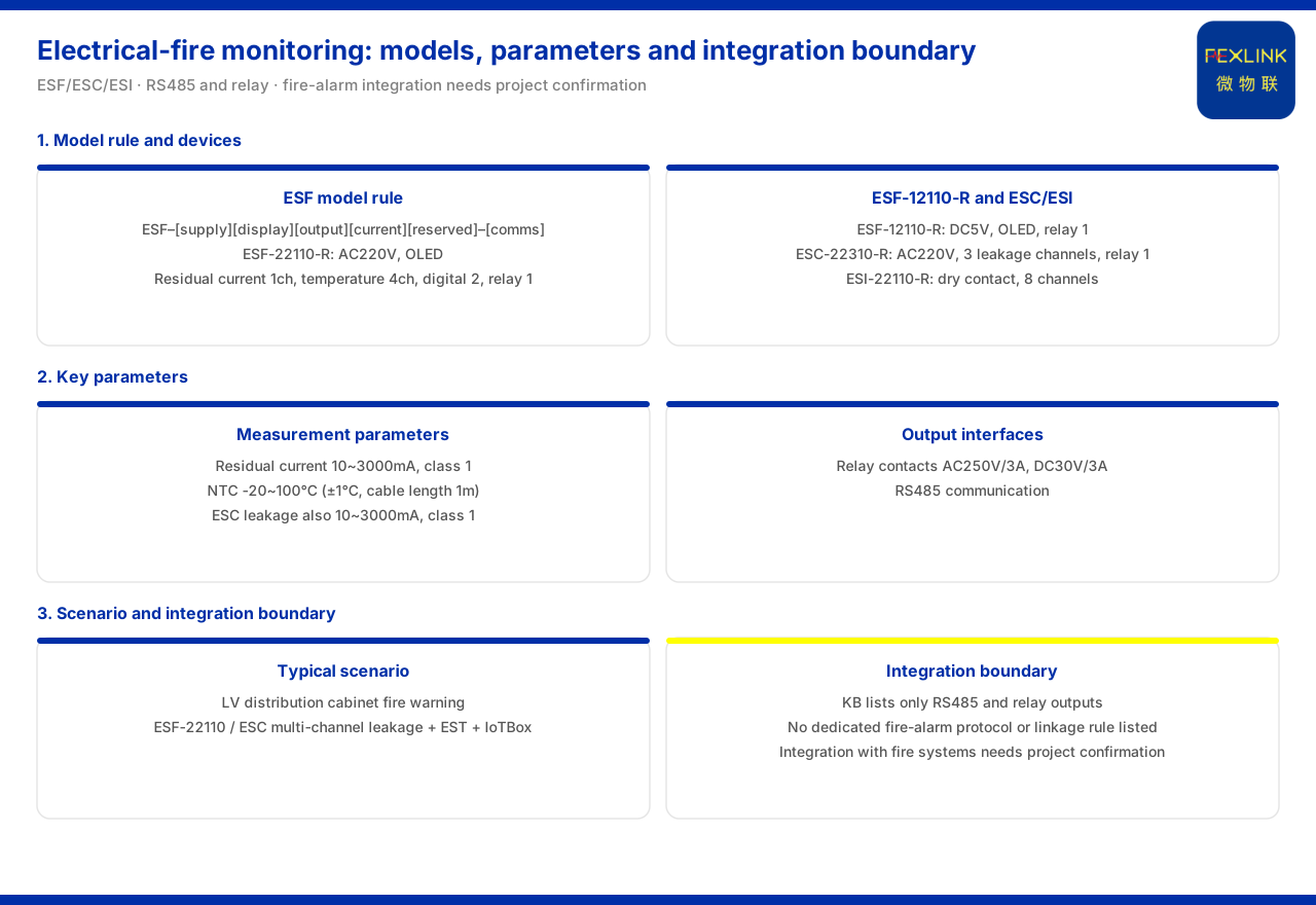
What electrical fire monitoring can do and whether it can connect directly to a fire-control host are the two questions most often asked of this product line. The electrical-fire-related devices given by the product knowledge base are mainly three classes: the ESF electrical fire monitoring and control device, the ESC multi-channel leakage monitoring and control device, and the ESI digital-status monitor. Taking the ESF electrical fire monitoring and control device (ESF-22110-R) as an example, its configuration is AC220V supply, OLED display, one residual-current channel, four temperature channels, two digital inputs, one relay output and RS485 communication; the ESC multi-channel leakage monitoring and control device (ESC-22310-R) is AC220V, OLED, three leakage channels and one relay output; and the ESI digital-status monitor (ESI-22110-R) uses dry-contact inputs and is AC220V, OLED, eight channels. On key parameters, the ESF residual-current measurement range is 10 to 3000mA with accuracy class 1, the NTC temperature range is minus 20 to 100 degrees Celsius, and the relay contact capacity is AC250V/3A and DC30V/3A; the ESC leakage measurement range is likewise 10 to 3000mA with accuracy class 1. As for connecting to a fire-control host, the product knowledge base lists only RS485 communication and relay output and does not record a dedicated interfacing protocol, linkage convention or interface definition with a fire alarm control unit or fire-control host, so such interfacing requires project-level confirmation.
1. The electrical fire monitoring and control device: model rules and key parameters
The ESF electrical fire monitoring and control device is the core device of electrical fire monitoring. The model rules given by the product knowledge base encode power, display, output, current parameter and reserved position into the model, where the current-parameter position corresponds to 10 to 3000mA and 5A/0.5mA. Among the models listed, the ESF electrical fire monitoring and control device (ESF-22110-R) is AC220V-supplied, with OLED display, one residual-current channel, four temperature channels, two digital inputs, one relay output and RS485 communication; the ESF electrical fire monitoring and control device (ESF-12110-R) is DC5V-supplied with OLED display and one relay output. On key parameters, the residual-current measurement range is 10 to 3000mA with accuracy class 1; the NTC temperature range is minus 20 to 100 degrees Celsius with ±1 degree Celsius accuracy and an external wire length of 1 metre; and the relay contact capacity is AC250V/3A and DC30V/3A. The measurement output interfaces are thus the relay and RS485.
2. The multi-channel leakage monitoring and control device: the capability of ESC
If several leakage channels are to be monitored at once, the ESC multi-channel leakage monitoring and control device can be chosen. The product knowledge base records that its leakage measurement range is 10 to 3000mA with accuracy class 1, and that its relay contact capacity is likewise AC250V/3A and DC30V/3A. Among the models listed, the ESC multi-channel leakage monitoring and control device (ESC-22310-R) is AC220V, OLED, three channels and one relay output; the ESC multi-channel leakage monitoring and control device (ESC-12111-R) and ESC-12311-R are DC5V, OLED, one or three channels and one relay output. The difference between ESC and ESF lies mainly in the measurement object and channel count: ESF emphasises residual current plus temperature and digital inputs, while ESC emphasises multi-channel leakage. In selection, weigh one against the other by the number of circuits to be monitored.
3. The digital-status monitor: ESI collects external states
Beyond electrical-quantity monitoring, sites often have digital or status quantities to collect. The product knowledge base records that the ESI digital-status monitor uses dry-contact inputs, and the models listed include the ESI digital-status monitor (ESI-22110-R) which is AC220V, OLED and eight channels; ESI-11110-R which is DC5V, digital tube and ten channels; ESI-21110-R which is AC220V and ten channels; and ESI-21210-R which is AC220V and twelve channels. Dry-contact input means it collects the open or closed state of an external switch, and can bring status quantities such as breaker position and alarm contacts into monitoring. In selection, choose among the four types by the number of contacts to be collected and the supply method.
4. Typical scenario: low-voltage distribution cabinet electrical fire early warning
The typical application scenarios of the product knowledge base list the recommended combination for "low-voltage distribution cabinet electrical fire early warning" as ESF-22110, ESC multi-channel leakage, EST temperature and IoTBox. In this low-voltage distribution cabinet scenario, electrical fire monitoring is carried by the above monitoring and control devices: ESF handles residual current and the related inputs, ESC handles multi-channel leakage, EST handles temperature and IoTBox handles aggregation and uplink. Reading this recommended combination shows that electrical fire monitoring is not the work of a single device but a combination of monitoring plus aggregation. In configuration, follow the scenario's combination logic: first determine the electrical quantities to be monitored, then map them one by one to devices.
5. Interfacing with a fire-control host: the boundary of the knowledge base
Interfacing with a fire-control host is a common requirement, but the boundary must be held according to what the knowledge base records. In the entries relating to ESF and ESC, the product knowledge base lists only RS485 communication and relay output, that is, a relay with a contact capacity of AC250V/3A and DC30V/3A and an RS485 interface; it does not record a dedicated interfacing protocol, linkage convention or interface definition with a fire alarm control unit or fire-control host. This means the electrical fire monitoring device provides general communication and contact interfaces to the outside, and whether and how it can connect to a fire-control host is not within the information listed by the knowledge base. If a project requires linkage with a fire-control host, the protocol and interface must be confirmed separately at the project level, and it must not be inferred from the existing entries that a certain fire-control linkage is already supported.
6. Front-end-layer protocol access: project-level confirmation
From the system-access perspective, the front-end layer L1 access layer of the product knowledge base lists more than 40 protocol parsers, including Modbus, MQTT, OPC-UA, 104 and BACnet; the Taiyi intelligent control hub system likewise lists more than 40 protocol accesses. The platform side thus has broad protocol-access capability, but this list does not separately include a fire-control host protocol. Electrical fire monitoring data still requires project-level confirmation to enter a fire-control system. In practice, the device-side general interfaces are determined by the knowledge base, the platform-side protocol capability is given as a range by the knowledge base, and the specific fire-control host as an interfacing target needs separate verification and should not be assumed to be within the existing list.
7. Selection and verification order
Taken together, proceed in this order. First, define the electrical quantity to be monitored: residual current, leakage, temperature or an external digital quantity. Second, choose the device type by object: ESF for residual current and inputs, ESC for multi-channel leakage, and ESI for digital quantities. Third, determine the model and channel count by circuit and contact numbers. Fourth, fix the AC220V or DC5V version by the on-site supply. Fifth, check whether the relay contact capacity and RS485 interface meet the linkage and networking needs. Sixth, if a fire-control host is to be interfaced, confirm the protocol and interface at the project level first, then decide the access method. By this order, device-side selection and system-side interfacing each have their basis.
Scope and limitations
First, this article restates only what the product knowledge base records; the factual boundary is limited to the records of ESF, ESC and ESI models and key parameters, the typical scenario, and the front-end-layer protocol list.
Second, the residual-current and leakage ranges, accuracy, NTC temperature measurement and relay contact capacity of ESF and ESC, and the supply, display, channel count and output of each model, are cited as listed, without inferring unlisted parameters.
Third, the dry-contact input and the channel count, supply and display of each ESI model are cited as listed.
Fourth, the recommended combination for low-voltage distribution cabinet electrical fire early warning, and the protocol-access lists of the front-end layer and the hub system, are cited as listed; this article does not infer a fire-control-host interfacing protocol from them.
Fifth, this article only explains the selection and interfacing boundary of electrical fire monitoring devices; it provides no linkage scheme, protocol configuration or setting scheme for a specific project, and related conclusions must be determined with site conditions and the project scheme.