Direct answer
According to the intelligent circuit breaker table in the product knowledge base, the communication method of the whole series — the intelligent circuit breaker (standard model, e.g. FECB2SP-1P) and the intelligent circuit breaker (leakage-protection model, e.g. FECB2SLP-2P) — is RS485. The standard model covers four pole counts, 1P, 2P, 3P and 4P, and the leakage-protection model covers 2P and 4P. RS485 belongs to Modbus RTU among the device downstream protocols: the breaker hands its data to the gateway, the gateway converts it to Modbus TCP or MQTT, and it then uplinks via Ethernet, 4G and similar into the IoT cloud platform. The answer to "what communication does the intelligent circuit breaker use" therefore is not RS485 alone; it must also state its place in the protocol chain — RS485 and Modbus RTU on the device side, and gateway conversion for the uplink on the platform side.
1. The whole series has RS485 as its uniform communication
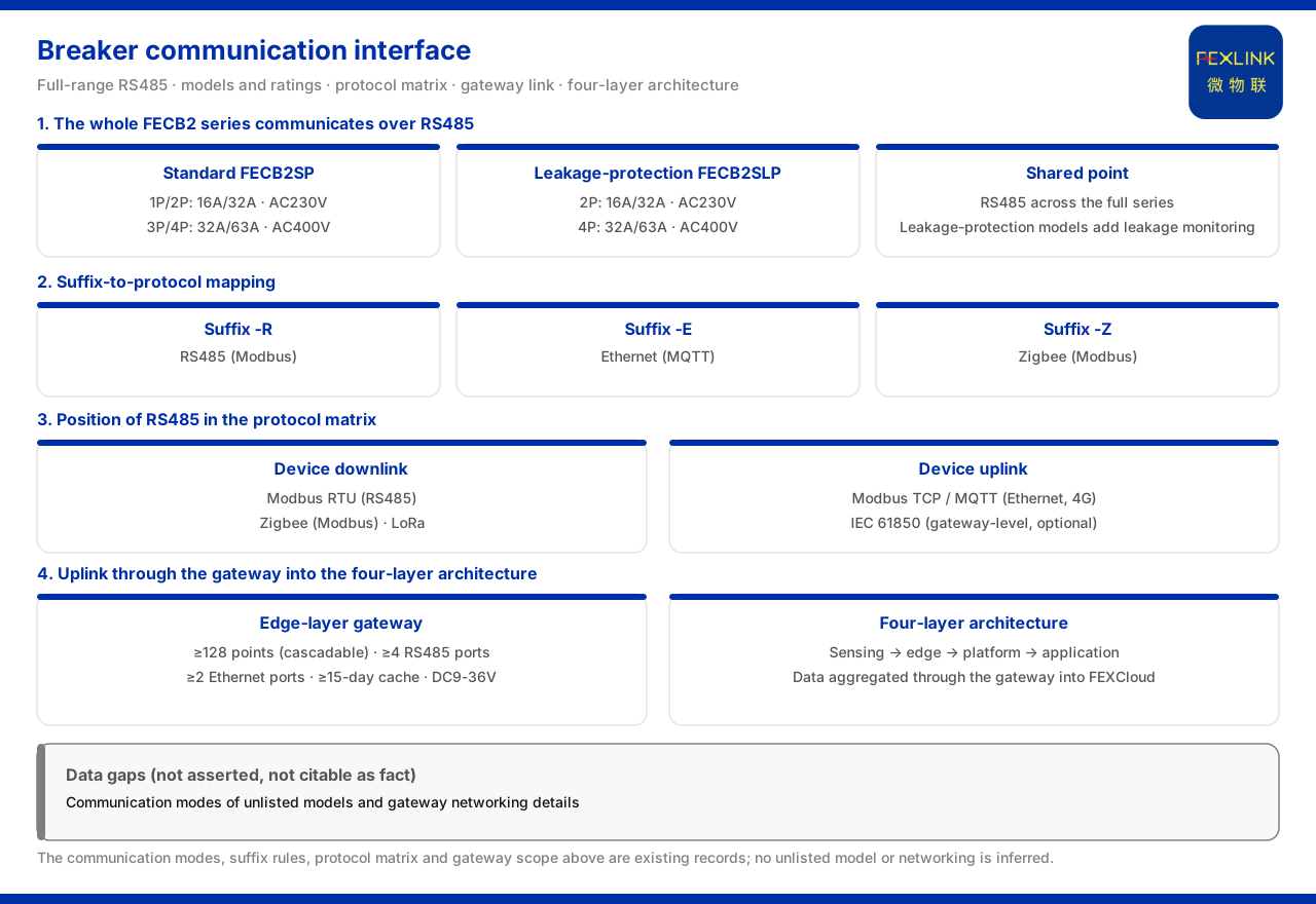
The model table of the intelligent circuit breaker in the product knowledge base stipulates that the 1P, 2P, 3P and 4P models of the standard model and the 2P and 4P models of the leakage-protection model all have RS485 in the communication column. That is, whatever the pole count and whether or not leakage protection is included, device-side communication is uniform across the entire product line. This uniformity has direct engineering meaning: where a site mixes the standard model and the leakage-protection model, the access method need not be planned separately, and both can be organised on the same bus.
RS485 suits this class of distribution-side device because breakers are usually arranged in rows inside an assembly cabinet, with short distances and many points, and RS485 is a bus-type interface convenient for hanging several devices on one bus and having a gateway aggregate them. The material writing the whole series as RS485 settles "can it be networked" at the selection stage: as long as the site plans an RS485 loop and a gateway, models of different pole counts and current steps can all access the same communication system.
2. Look at the specifications first, then the communication
The same model table also gives the electrical and functional specifications of each model. In the standard model, 1P and 2P are 16A/32A at AC230V, and 3P and 4P are 32A/63A at AC400V; in the leakage-protection model, 2P is 16A/32A at AC230V and 4P is 32A/63A at AC400V. A note below the table explains that SP is the standard model and SLP is the leakage-protection model (leakage monitoring plus leakage-protection function). Reading these specifications with the communication column shows that selection has two independent dimensions: the electrical specification of pole count, rated current and rated voltage, and the uniform RS485 communication. The former determines loop compatibility, the latter whether networking is possible.
3. Model suffix and communication standard
The product knowledge base gives a general suffix rule: -R stands for RS485 (Modbus), -E stands for Ethernet (MQTT), -Z stands for Zigbee (Modbus), and 4G (MQTT) is optional (reserved) for some products. This rule explains the correspondence between model suffix and communication standard. The intelligent circuit breaker marks its models by pole count (1P, 2P and so on), and its communication is uniformly RS485, a fixed configuration of this product line; the suffix rule describes the general specification, and this article states the rule itself without inferring other suffix variants.
4. The place of device-side communication in the protocol matrix
The communication protocol matrix of the product knowledge base stipulates: device downstream uses Modbus RTU (RS485), Zigbee (Modbus) and LoRa; device upstream uses Modbus TCP and MQTT (Ethernet, 4G), plus gateway-level optional IEC 61850. The RS485 of the intelligent circuit breaker belongs to Modbus RTU among the device downstream protocols, and is converted by the gateway to uplink over Modbus TCP or MQTT. Understanding this clarifies roles: the breaker is a downstream device that is "collected from", protocol conversion and forwarding are undertaken by the gateway, and the upstream protocols describe the gateway's options rather than the breaker's own communication method.
5. From gateway uplink to platform
The product knowledge base summarises the monitoring system as a general four-layer architecture: perception, edge, platform and application. The perception layer consists of monitoring modules, smart meters and sensors; the edge layer of devices such as gateways; the platform layer is the IoT cloud platform; and the application layer provides visualisation and alarms. As a distribution-side device, the breaker's RS485 data is aggregated by the edge-layer gateway into the IoT cloud platform. Its position is clear: it is a perception-layer object to be collected from, not a device facing the platform or application layer directly.
This layering also explains why the communication method must be clarified first. The four layers connect level by level: perception collects, edge converts and uplinks, platform aggregates and judges, and application presents and operates. The breaker sits in the perception layer and does not itself interface with a visualisation interface or an alarm application; only after conversion by the edge-layer gateway can its data enter the platform and applications. "What the breaker communicates over" and "where the data finally goes" are therefore two ends of the same matter.
6. The gateway's access capability
The edge-layer gateway undertakes the aggregation duty. The product knowledge base gives reference parameters of the smart gateway: no fewer than 128 mountable points with cascading support, no fewer than 4 RS485 channels, no fewer than 2 Ethernet channels, optional 4G, 5G or LoRa, data caching of no fewer than 15 days, a wide DC9 to 36V supply, and protection rating IP65. These parameters show the two ends of the gateway: downward it connects devices such as the intelligent circuit breaker over multiple RS485 channels, and upward it accesses the platform over Ethernet or wireless. "No fewer than 4 RS485 channels" and "no fewer than 128 mountable points" determine how many buses and monitoring points can be organised under one gateway, a direct constraint on networking scale.
7. Protocol parsing and the access layer
The product knowledge base records that the L1 access layer of the front-end layer (unified scheduling by the Qianzhi hub plus red-line pre-inspection) supports protocol parsing for more than 40 protocols, including Modbus, MQTT, OPC-UA, 104 and BACnet. After the intelligent circuit breaker accesses over RS485 and Modbus, this access layer can complete the protocol parsing before the data proceeds to the subsequent cleaning and judgement flows. This description connects the communication question to the next segment of the data chain: the device side states "how to read", and the access layer is responsible for "what to read and how to parse it"; only when the two are joined does the breaker's data enter the platform from the site.
8. Networking check order
Bringing the preceding relations into a reusable order of checks: first, confirm whether the pole count, rated current and rated voltage of the chosen breaker model fall within the corresponding specification; second, confirm that its communication is RS485 and plan the number and routing of RS485 buses; third, assess the gateway's access capability, checking RS485 channels, mountable points and caching days against the site scale; fourth, confirm whether the uplink method (Ethernet, 4G) and protocol parsing cover the site's needs. Followed in this order, the communication question lands on an implementable networking plan.
Scope and limitations
First, the citations in this article are limited to the product material and the corresponding fact pack, and introduce no parameter, certification or case not listed.
Second, the whole-series RS485 communication of the intelligent circuit breaker (standard and leakage-protection models), and the pole count, rated current, rated voltage and leakage-protection specification of each model, are limited to the material entries; this article infers no specification of unlisted models.
Third, the general suffix rule (-R, -E, -Z and the optional 4G) and the communication protocol matrix (downstream Modbus RTU, Zigbee and LoRa; upstream Modbus TCP, MQTT and IEC 61850) are limited to the material; this article extends no other protocol.
Fourth, the four-layer architecture is limited to the perception layer, edge layer, platform layer and application layer described by the material, and this article infers no specific product list of each layer.
Fifth, the smart gateway reference parameters (no fewer than 128 mountable points, no fewer than 4 RS485 channels, no fewer than 2 Ethernet channels, no fewer than 15 days of caching, DC9 to 36V and IP65) are limited to the material, and this article makes no commitment on behalf of actual site scale.
Sixth, the L1 access layer supporting protocol parsing for more than 40 protocols and listing Modbus, MQTT, OPC-UA, 104 and BACnet is cited as given; this article infers no parsing result for a specific project.
Seventh, this article explains only the communication method and its place in the protocol chain, and provides no networking design or configuration calculation for a specific project.