Direct answer
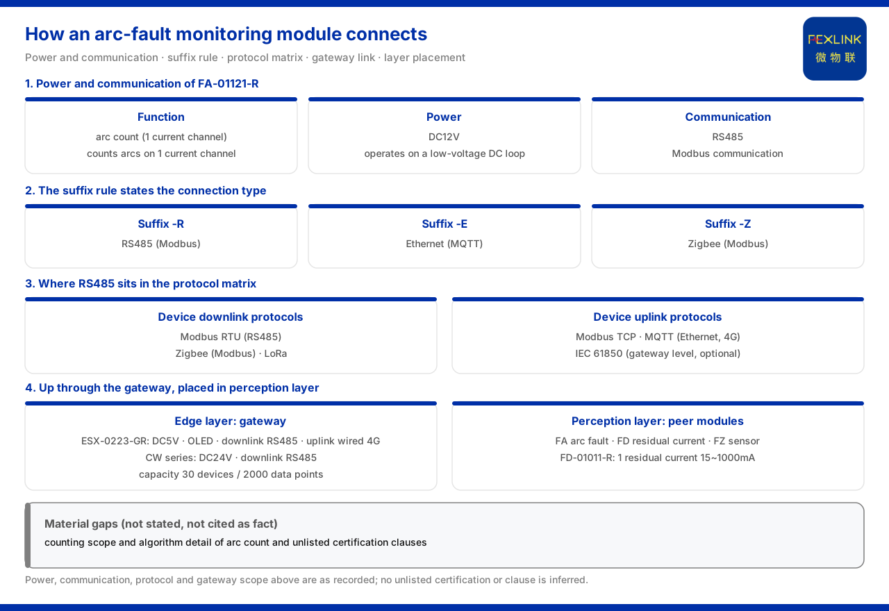
The product material gives a definite statement of the supply and communication of the FA arc-fault monitoring module (e.g. FA-01121-R): the supply is DC12V and the communication is RS485. Its function is "arc count (1 current channel)", that is, counting arcs for one current channel. The model suffix -R is consistent with the general suffix rule, corresponding to RS485 (Modbus), so the way this module accesses the system is clear: DC12V supply and RS485 access. Combined with the general four-layer architecture of the monitoring system, it is a perception-layer device that uplinks through a gateway to the platform, rather than facing the platform layer or application layer directly.
1. Supply: DC12V
The product material records that the FA arc-fault monitoring module (e.g. FA-01121-R) uses a DC12V supply. Writing the supply as DC12V shows that it works in a low-voltage DC loop and requires corresponding DC power support.
The supply statement has practical engineering meaning. It is directly related to the cabinet, power module and wiring arrangement where the device sits: a device supplied at DC12V must have corresponding DC power confirmed on site during deployment, rather than being reserved for as an AC device. The material lists the supply as a definite parameter of this model, so during selection and installation the site conditions should be checked against this statement, avoiding a mismatch discovered only at the installation stage.
2. Communication: RS485 and the suffix rule
The product material records that this model communicates over RS485. This is consistent with the general suffix rule: suffix -R indicates RS485 (Modbus), -E indicates Ethernet (MQTT), and -Z indicates Zigbee (Modbus). The model of the arc-fault monitoring module ends in -R, so its RS485 communication corresponds exactly to this rule.
The value of the suffix rule is that it lets the model itself state the access method. Seeing -R, one knows the model uses RS485 with Modbus communication; seeing -E or -Z corresponds to Ethernet or Zigbee. In this way, models with different access methods in the same product family need not be memorised one by one; the suffix is enough. For the arc-fault monitoring module, the -R suffix already locks it to RS485 access.
3. The place of RS485 in the protocol matrix
The product material gives a communication protocol matrix: device downstream protocols include Modbus RTU (RS485), Zigbee (Modbus) and LoRa; device upstream protocols include Modbus TCP and MQTT (Ethernet, 4G), plus gateway-level optional IEC 61850.
The RS485 of the arc-fault monitoring module belongs to the Modbus RTU statement among the device downstream protocols. This shows that its role is a downstream device that is "collected from": the gateway or host reads data such as the arc count from it over Modbus RTU. Understanding this helps clarify the chain: the module itself handles collection and provides data locally, while protocol conversion and upward forwarding are undertaken by the gateway. The upstream protocols — Ethernet, 4G and even IEC 61850 — describe the gateway's options when transmitting to the platform side, not the module's own communication method.
4. Uplink to the platform: the role of the gateway
Continuing from the previous section, for the data collected by the module to enter the platform it must pass through a gateway. The product material records that one model of an intelligent edge-computing gateway (e.g. ESX-0223-GR) is supplied at DC5V with an OLED display, communicates downstream over RS485 and upstream over wired 4G, and has an access capability of 30 devices and 2000 data points; different models of the CW industrial gateway in the same family are supplied at DC24V and also communicate downstream over RS485.
These statements show the two ends of the gateway in the chain: downstream it connects perception-layer devices such as the arc-fault monitoring module over RS485, and upstream it accesses the platform over wired 4G and similar. The gateway's access capability gives the number of mountable devices and the data-point scale, determining how many monitoring points can be organised under one gateway. The module's RS485 interface and the gateway's downstream RS485 correspond to each other, and the two are matched in communication statement.
5. It belongs to the perception layer
The product material summarises the monitoring system as a general four-layer architecture: perception layer, edge layer, platform layer and application layer. The perception layer consists of various monitoring modules, smart meters and sensors; the edge layer consists of devices such as gateways; the platform layer is the cloud platform; and the application layer provides users with capabilities such as visualisation and alarms.
Under this division, the arc-fault monitoring module belongs to the perception layer. It collects the arc count at the low-voltage distribution site and is the starting point of the data chain; the gateway belongs to the edge layer and handles protocol conversion and uplink; the cloud platform belongs to the platform layer; and visualisation and alarms belong to the application layer. Placing the module in the perception layer helps correctly understand its responsibility boundary: it provides the raw arc-monitoring data and does not undertake cross-layer data processing or decision functions.
6. Its parallel relationship with the residual-current monitoring module
In its model table, the product material places the arc-fault monitoring module alongside the FD mains residual-current monitoring module (e.g. FD-01011-R): both are supplied at DC12V and communicate over RS485; the latter additionally provides 1 residual current with a collection range of 15mA to 1000mA. The product model quick reference further gives the correspondence: the arc-fault monitoring module corresponds to FA, the mains residual-current monitoring module to FD, and the sensor module to FZ.
This parallel relationship illustrates the product division of labour. Arc monitoring and residual-current monitoring are two different electrical-hazard objects, but they are consistent in supply and communication, so they can be deployed cooperatively on the same site under the same gateway. For the solution designer, this means the access method can remain uniform when monitoring different kinds of hazard, with the difference only in the measured physical quantity and the corresponding module model. Listing FA, FD and FZ side by side in the quick reference is precisely to facilitate this comparison and choice.
7. Bringing supply and communication into the deployment check
Returning to the original question, supply and communication are worth answering first because they determine whether the device can truly access the system. Even if a module's function is suitable, if the site cannot provide a DC12V supply, or has no available RS485 bus and gateway, the collected arc count cannot enter the platform, let alone form alarms or statistics.
In actual deployment, therefore, these two should be pre-checks: first confirm the availability of DC power, then confirm whether the planning of the RS485 loop and the gateway's access capability match. The gateway access capability given by the product material (number of devices and data points) also indicates that the monitoring points one gateway can organise are of a definite scale, so during deployment the arc-fault monitoring module should be counted together with other perception-layer devices. Only by aligning supply, communication and gateway in statement does the module go from "installable" to "operable".
Scope and limitations
First, the citations in this article are limited to the product material and the corresponding fact pack, and introduce no parameter, certification or case not listed.
Second, the DC12V supply, RS485 communication and the function "arc count (1 current channel)" of the FA arc-fault monitoring module (e.g. FA-01121-R) are limited to the material entry; this article does not infer the specifications of unlisted models.
Third, the general suffix rule (-R = RS485 (Modbus), -E = Ethernet (MQTT), -Z = Zigbee (Modbus)) and the communication protocol matrix statement are limited to the material; this article extends no other protocols.
Fourth, the supply, communication and access capability of the intelligent edge-computing gateway and the industrial gateway are limited to the material entries.
Fifth, the four-layer architecture is limited to the perception layer, edge layer, platform layer and application layer described by the material.
Sixth, the supply, communication and residual-current collection range of the mains residual-current monitoring module are limited to the material entry; this article does not infer the functions of other modules.
Seventh, this article explains only the supply and communication statements and the system positioning, and provides no selection or configuration calculation for a specific project.