Direct answer
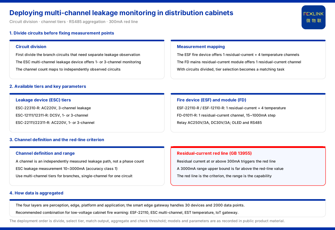
Deployment of multi-channel leakage monitoring in a distribution cabinet can follow the order of "first divide measuring points by branch circuit, then choose the product rating by circuit count, and finally aggregate into a gateway or platform over RS485". The knowledge base records that the ESC multi-channel leakage-current monitoring & control device (e.g. ESC-22310-R) provides 1-channel or 3-channel leakage monitoring; the ESF electrical fire monitoring & control device (e.g. ESF-22110-R) provides 1-channel residual current plus 4-channel temperature monitoring; and the FD mains residual-current monitoring module (e.g. FD-01011-R) provides 1-channel residual current. Accordingly, a single-phase or single-branch circuit can choose a 1-channel rating, a three-phase or multi-branch circuit can choose a 3-channel rating, and ESF is used when temperature must also be monitored. The knowledge base does not give a decision rule for "which rating must be chosen under which circuit conditions"; the deployment order in this article is an application-layer extrapolation.
First divide circuits, then set measuring points
The premise of multi-channel monitoring is to divide clearly the branch circuits to be observed in the distribution cabinet: which circuits need independent leakage metering and which can be observed together. The knowledge base gives product ratings in the form of "channel count", which exactly matches this division — ESC provides 1-channel or 3-channel leakage monitoring; ESF provides 1-channel residual current and 4-channel temperature; FD provides 1-channel residual current. Once circuits are divided, product ratings have a correspondence. If a product is picked before measuring points are considered, the rating may not match the actual circuit count; dividing circuits first turns rating selection into a matching task.
Available product ratings
The knowledge base model table of multi-channel leakage-current monitoring & control devices lists: the ESC multi-channel leakage monitoring device (ESC-22310-R) as AC220V, 3-channel leakage; the ESC multi-channel leakage monitoring device (ESC-12111/12311) as DC5V, 1-channel or 3-channel leakage; the ESC multi-channel leakage monitoring device (ESC-22111/22311) as AC220V, 1-channel or 3-channel leakage. Each type has an OLED display, 1-channel relay output and RS485 communication. The electrical fire monitoring & control devices ESF-22110-R as AC220V and ESF-12110-R as DC5V both include 1-channel residual current, 4-channel temperature, OLED display, 1-channel relay output and RS485 communication. FD-01011-R provides 1-channel residual current with an acquisition range of 15mA to 1000mA, i.e. the 10mA to 1000mA rating, with DC12V power and RS485 communication; the product outline positions it as a residual-current monitoring module with a range of 10mA to 1000mA.
What channel count actually describes
The knowledge base uses "channel count" to describe the number of leakage circuits that can be monitored simultaneously: ESC is 1 or 3 channels, ESF is 1-channel residual current, and FD is 1-channel residual current. The key to understanding channel count is to map it to the branch circuits in the distribution cabinet: 1 channel means only one circuit can be observed, and 3 channels means three circuits can be observed independently. Channel count is not equivalent to phase count but is the number of independently meterable channels. Therefore, when several branches in a distribution cabinet need separate leakage attention, a multi-channel rating should be preferred; when only the total circuit or a single circuit needs observation, a single-channel rating is enough. Understanding "channel" as an independently observable unit avoids confusing ratings with phase count.
Pairing multiple and single channels
The knowledge base gives channel configurations for three product types, showing that deployment can be combined as needed: when there are many leakage circuits, use the multi-channel ESC rating for centralized monitoring; when residual current and temperature must be monitored simultaneously, use ESF, whose 1-channel residual current is paired with 4-channel temperature; when only single-point residual current is needed, use FD. The three types share OLED display, relay output and RS485 communication, so they can be deployed in a mix within the same system. When combining, note that the channel conventions differ: the channels of ESC are leakage channels, ESF is 1-channel residual current plus 4-channel temperature, and FD is 1-channel residual current; the "channels" of different products must not be directly added as a unified channel count.
Key parameters and alarm output
The knowledge base gives the key parameters of ESC: leakage measurement 10mA to 3000mA, accuracy class 1; relay contact capacity AC250V and 3A, DC30V and 3A. These parameters determine the measurement coverage and the load the relay can drive. During deployment, the measurement range should be chosen by the expected leakage magnitude of the branch circuit, and the relay contact capacity should be calculated by the load to be linked; if the linked load exceeds the capacity, it should be handled separately. The OLED display and relay output configuration let these devices both be read locally and issue switching actions externally.
Residual-current threshold red line
The knowledge base records that the residual-current red line is triggered as a non-overridable red line when residual current reaches or exceeds 300mA, based on GB 13955; the basic vital-sign sub-model is leakage, using time-series trends plus a pre-criterion. This provides a criterion source for leakage monitoring: whether 1 channel or multiple channels are used, residual current reaching the red-line value should trigger an alarm. Setting the threshold by the red-line convention during deployment keeps multi-channel monitoring consistent with the unified criterion and avoids differing criterion conventions due to different channel counts. It should be noted that the upper limit of the ESC leakage measurement range is far above the 300mA red-line value, so the device range is sufficient to cover the red-line criterion; the red line is a criterion and the range is measurement capability, and the two should not be confused. In multi-channel deployment, every channel should be handled by the same red-line criterion, not with a standard set separately by each reading.
How to aggregate
The knowledge base divides the general four-layer architecture of the monitoring system into perception layer, edge layer, platform layer and application layer; the access capability of the intelligent edge-computing gateway is 30 devices and 2000 data points. The RS485 output of each ESC, ESF and FD type can be aggregated into a gateway or platform for unified collection of multiple measuring points. The typical application scenario and selection comparison table in the knowledge base lists the recommended combination for "low-voltage distribution cabinet electrical fire pre-warning" as ESF-22110, ESC multi-channel leakage, plus temperature monitoring (EST) and an IoT gateway. By this combination, the three data types of residual current, leakage and temperature can be collected in the same system. The point of aggregation is that only when multi-channel data are compared on the same time axis can one distinguish an isolated anomaly of a single circuit from a systematic change appearing simultaneously on multiple circuits. If the data of each channel are scattered across different systems, horizontal comparison cannot be performed.
Deployment order
Drawing the above together, deployment can follow the order of "divide circuits, choose ratings, configure output, set aggregation, check threshold": first divide the leakage circuits that need independent monitoring; then choose among the ESC 1-channel or 3-channel ratings by circuit count, and pair with ESF when temperature must also be monitored; confirm that the relay output matches the load to be linked; aggregate the RS485 into a gateway or platform for unified collection; and finally confirm that the residual-current threshold is set by the red-line convention. The knowledge base does not give a decision rule for choosing a rating by field conditions; the order above is an application-layer extrapolation, and actual deployment should be determined together with the field distribution structure. After deployment, the readings of each channel should also be periodically checked against the circuit division, to avoid the rating being disconnected from actual circuits due to wiring changes.
Scope and limitations
- The channel counts, parameters, models, architecture and thresholds in this article are limited to the existing records of the knowledge base, and do not introduce standard clauses or selection thresholds not listed there. - The knowledge base does not define a decision rule for "which rating must be chosen under which circuit conditions"; the deployment order in the text is an application-layer extrapolation. - The red-line threshold in the text is an existing statement of the knowledge base and does not constitute a rectification or result commitment for a specific project. - Actual deployment and selection must be verified by the electrical-safety engineering party together with the field distribution structure and standard conventions.