
Direct Answer
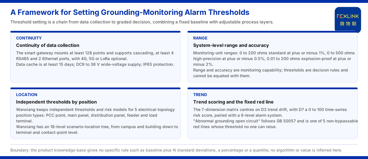
For setting grounding monitoring alarm thresholds, the product knowledge base gives a method framework rather than a ready-made set of values. The framework has four layers of basis. First, the safety red-line layer, namely "abnormal open-circuit of grounding resistance" based on GB 50057, which is the non-adjustable part. Second, the system-level range and accuracy layer, with the monitoring unit offering three references: a standard type from 0 to 200 ohm, a high-accuracy type from 0 to 500 ohm, and an explosion-proof type from 0.01 to 200 ohm. Third, the position-type layer, in which the Wanxiang engine maintains independent thresholds for five electrical topology position types. Fourth, the trend and scoring layer, centred on the trend drift of the 7-dimensional perception matrix and paired with the 6-level alarm. The condition of continuous data acquisition is carried by the smart gateway, whose specifications such as mounting not fewer than 128 points and a data cache of not fewer than 15 days provide the hardware basis for baseline accumulation. It should be noted that the product knowledge base gives no rule for setting concrete threshold values, so this article only sets out the framework and does not infer an algorithm or a value.
1. Why Threshold Setting Needs a Framework
The alarm threshold of grounding monitoring cannot be produced out of thin air; it has to satisfy several conditions at once: the data must be continuous, the points must be distinguishable, the standard baseline must be held, and a slow change must also be visible. The product knowledge base lands these matters on products, position models and judgement rules respectively. Understanding this prevents treating a "threshold" as an isolated number and instead treats it as a chain from data acquisition to judgement grading. This article follows the order of that chain, restates what the product knowledge base lists layer by layer, and makes clear that it adds no numerical rule not listed there.
2. The Continuity Basis of Data Acquisition
A threshold relies on data accumulation. The product knowledge base gives the smart gateway specifications of the grounding resistance monitoring system: mounting not fewer than 128 points and cascade-capable, not fewer than four RS485 channels, not fewer than two Ethernet channels, optional 4G, 5G and LoRa, a data cache of not fewer than 15 days, a DC9 to 36 volt wide-voltage supply, and a protection rating of IP65. These specifications show that the system has the capability of continuous acquisition and cache over a certain period, providing the condition for accumulating a threshold baseline and preserving data during a network outage. The product knowledge base gives no concrete way of computing a threshold baseline, so this article cites only the acquisition and cache capability and does not infer how a baseline is formed.
3. System-Level Range and Accuracy Baseline
Before setting a threshold, the range the monitoring can cover must be known. The grounding resistance monitoring system of the product knowledge base gives reference parameters: the monitoring unit has a standard type from 0 to 200 ohm with an accuracy of plus or minus one percent; a high-accuracy type from 0 to 500 ohm with an accuracy of plus or minus zero point five percent; and an explosion-proof type from 0.01 to 200 ohm with an accuracy of plus or minus two percent. Range and accuracy are the system-level baseline when setting a grounding monitoring threshold: the threshold must fall within the monitorable range, and its resolution is constrained by the accuracy. What must be distinguished is that range and accuracy are monitoring capability while the threshold is a judgement rule, and the two cannot be equated. The product knowledge base gives no value of how many ohm should be set for each grounding grid, and this article does not add one.
4. Independent Thresholds by Position Type
The product knowledge base records that the position awareness of the Wanxiang engine covers five electrical topology position types, namely the PCC point, the main distribution panel, the sub-distribution panel, the feeder and the load terminal, and maintains independent thresholds and risk models for each. Further, the product knowledge base records that the Wanxiang engine has an 18-level scene positioning tree that locates progressively from the park and the building and can reach down to the terminal-block level and the contact-point level. This means that the grounding monitoring threshold can be implemented at a concrete point rather than applying one set of criteria to the whole system. Positions differ, loads and topologies differ, and the consequences of a grounding anomaly differ, so setting thresholds by type is precisely meant to match that difference. The product knowledge base gives no concrete threshold for each position type, so this article cites only the framework of type division and level-based positioning.
5. The Grading Framework of Trend and Score
Beyond position typing, the product knowledge base also gives a judgement framework that changes over time. It records that the 7-dimensional perception matrix takes D3 trend drift as the core dimension and D7 as a time-series risk score from 0 to 100, paired with the 6-level alarm system, namely normal, attention, YJ1, YJ2, BJ1 and BJ2. The thresholds of the slow-drift class in grounding monitoring can be set against the trend and scoring framework: first see whether a slow drift occurs, then see which level the score falls into. In this way a threshold is not merely "alarm when a certain number is exceeded" but is associated with direction and grading. The product knowledge base gives no conversion relationship between the score and a concrete resistance value, so this article does not infer a conversion rule.
6. The Boundary between the Non-Adjustable and the Adjustable
On top of the above framework, the safety red-line must also be revisited. The product knowledge base records that "abnormal open-circuit of grounding resistance" is based on GB 50057, is one of five red-lines that cannot be bypassed, and that no one may raise its threshold. That is, part of the threshold-setting framework is unavailable: the safety red-line does not change with the position type or the score band. The complete picture of threshold setting is therefore "a non-adjustable baseline plus adjustable process layers": the baseline holds the standard requirement, while the process layer grades against the point and the trend. The product knowledge base gives no concrete setting rule for adjustable thresholds, so this article explains only that the two coexist and does not add rule details.
7. Boundaries That Must Be Held
The above can be reduced to a reading order. First, confirm the range and accuracy baseline and choose the standard type, the high-accuracy type or the explosion-proof type. Second, confirm the acquisition and cache conditions and understand the hardware prerequisite of baseline accumulation. Third, implement the thresholds by position type and scene positioning level. Fourth, set the slow-drift judgement by trend drift and the 6-level score. Fifth, return to the safety red-line and confirm that the non-adjustable part is not overridden by process settings. The boundary that must be held is this: the product knowledge base gives no concrete threshold-setting rule such as a baseline plus a multiple of the standard deviation, a percentage or a quantile, and this article does not infer a concrete algorithm or value.
Applicability and Limits
- This article restates only what the product knowledge base lists; its factual boundary is the records of the grounding resistance monitoring system reference parameters, the smart gateway specifications, the position awareness of the Wanxiang engine and the perception matrix of the Qianzhi engine. - The monitoring unit range and accuracy (standard type from 0 to 200 ohm at plus or minus one percent, high-accuracy type from 0 to 500 ohm at plus or minus zero point five percent, explosion-proof type from 0.01 to 200 ohm at plus or minus two percent) are cited under the listed convention as reference values and do not constitute an engineering commitment. - The smart gateway's mounting of not fewer than 128 points and cascade capability, not fewer than four RS485 channels, not fewer than two Ethernet channels, optional 4G, 5G and LoRa, a cache of not fewer than 15 days, a DC9 to 36 volt wide-voltage supply and IP65 are cited under the listed convention. - The independent thresholds of the five electrical topology position types and the 18-level scene positioning tree are cited under the listed convention; the concrete threshold of each position type is not added. - The 7-dimensional perception matrix centred on trend drift, the time-series risk score from 0 to 100 and the 6-level alarm system are cited as listed. - "Abnormal open-circuit of grounding resistance" being based on GB 50057 and non-raisable is cited under the listed convention; concrete trigger values are not restated. - The product knowledge base gives no rule for setting concrete threshold values, and this article accordingly declares that it sets out only a method framework and provides no algorithm or value.


