
FS Lightning-Protection Monitor
FS-33211
SPD online monitoring, microamp-accuracy leakage-current detection, supporting four/five-element and nine-element monitoring, full visibility of SPD status and life trend.
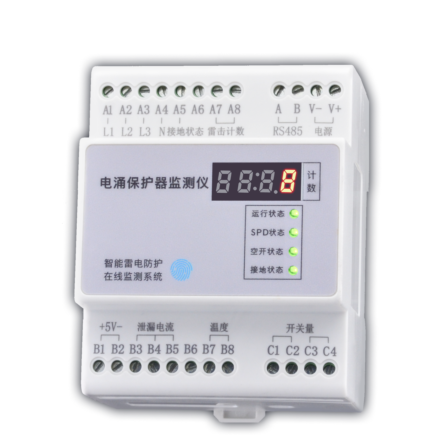
Product Overview
The FS Surge Protective Device Monitor collects SPD leakage current, temperature, voltage, lightning strike count, remote signaling and grounding status in real time, covering the core degradation indicators to replace manual inspections. It measures leakage current, SPD temperature and ambient temperature, SPD damage status, circuit breaker trip status, SPD false grounding and poor grounding status, and SPD discharge lightning strike count. It monitors the status of surge protective devices (SPDs), is generally installed indoors, and is typically mounted next to the surge protective device. It supports multiple communication methods including RS485 (Modbus), Zigbee and Ethernet (Modbus TCP/MQTT), and can connect to local monitoring or cloud platforms.
Core Capabilities
High-precision measurement of 3 leakage current channels (50~1500μA) and 2 temperature channels (-20~105℃). Lightning strike counting with minimum trigger of 0.1kA and counting range of 0~9999, displayed directly on the local digital tube. Remaining service life (0~100%) estimated from monitoring data, with early warning for replacement. Three independent status indicator lights for SPD, circuit breaker and grounding turn red for alarm, with configurable thresholds. Product Features
Data Generated
Product Features
Full-Parameter Monitoring
Supports high-precision measurement of 3 leakage current channels (50~1500μA) and 2 temperature channels (-20~105℃) to accurately sense SPD performance degradation.
Dual Leakage Current/Temperature Measurement
Independent monitoring of 3 leakage current channels and 2 temperature channels, covering the core SPD degradation indicators for accurate insight into operating health.
Accurate Lightning Strike Counting
Minimum trigger of 0.1kA and counting range of 0~9999, displayed directly on the local digital tube for easy strike frequency statistics and life assessment.
Service Life Estimation and Warning
Remaining service life (0~100%) estimated from monitoring data with early replacement alerts, preventing fires or equipment damage caused by lightning protection failure.
Local Audible and Visual Alarm
Three independent status indicator lights for SPD, circuit breaker and grounding turn red for alarm with configurable thresholds, enabling rapid on-site fault location without background queries.
Flexible Multi-Protocol Networking
Supports RS485 (Modbus), Zigbee and Ethernet (Modbus TCP/MQTT) for connection to local monitoring or cloud platforms. Selection Guide
System Topology
Selection Guide
Model Naming Rules
FS - 0 3 2 1 1 - R FS Product Lightning protection monitoring module 0 Voltage monitoring channels 0=None; 1=1 channel; 2=2 channels; 3=3 channels 3 Leakage current monitoring channels 0=None; 1=1 channel; 2=2 channels; 3=3 channels 2 Temperature monitoring channels 0=None; 1=1 channel; 2=2 channels 1 Four-element monitoring function 0=No; 1=Yes (remote signaling, circuit breaker, grounding, counting) 1 Power supply 1=DC12V; 2=AC220V; 3=Solar; 4=Lithium battery R Communication method R=RS485; E=Ethernet; Z=ZigBee; G=GPRS Model Installation environment Remote signaling/circuit breaker/grounding/counting Leakage current monitoring Temperature monitoring Voltage monitoring Service life estimation Communication method FS-00011-R Indoor version Supported --- --- --- --- RS485 Modbus FS-00011-Z Indoor version Supported --- --- --- --- Zigbee Modbus FS-00011-E Indoor version Supported --- --- --- --- Ethernet Modbus TCP/MQTT FS-03211-R Indoor version Supported 3 channels 2 channels --- Supported RS485 Modbus FS-03211-Z Indoor version Supported 3 channels 2 channels --- Supported Zigbee Modbus FS-03211-E Indoor version Supported 3 channels 2 channels --- Supported Ethernet Modbus TCP/MQTT FS-33211-R Indoor version Supported 3 channels 2 channels 3 channels Supported RS485 Modbus FS-33211-Z Indoor version Supported 3 channels 2 channels 3 channels Supported Zigbee Modbus FS-33211-E Indoor version Supported 3 channels 2 channels 3 channels Supported Ethernet Modbus TCP/MQTT Technical Parameters
| Model | Installation Environment / Remote Signaling/Circuit Breaker/Grounding/Counting / Leakage Current Monitoring / Temperature Monitoring / Voltage Monitoring / Service Life Estimation / Communication Method |
| FS-00011-R | Indoor version / Supported / --- / --- / --- / --- / RS485 Modbus |
| FS-00011-Z | Indoor version / Supported / --- / --- / --- / --- / Zigbee Modbus |
| FS-00011-E | Indoor version / Supported / --- / --- / --- / --- / Ethernet Modbus TCP/MQTT |
| FS-03211-R | Indoor version / Supported / 3 channels / 2 channels / --- / Supported / RS485 Modbus |
| FS-03211-Z | Indoor version / Supported / 3 channels / 2 channels / --- / Supported / Zigbee Modbus |
| FS-03211-E | Indoor version / Supported / 3 channels / 2 channels / --- / Supported / Ethernet Modbus TCP/MQTT |
| FS-33211-R | Indoor version / Supported / 3 channels / 2 channels / 3 channels / Supported / RS485 Modbus |
| FS-33211-Z | Indoor version / Supported / 3 channels / 2 channels / 3 channels / Supported / Zigbee Modbus |
| FS-33211-E | Indoor version / Supported / 3 channels / 2 channels / 3 channels / Supported / Ethernet Modbus TCP/MQTT |
Technical Parameters
Basic Parameters
Operating voltage DC 9~27V Product power consumption 1W Operating temperature -20℃~60℃ Operating humidity <95% Product weight 260g Dimensions 72*90*69mm (L×W×H) Housing material Thermoplastic UL94V0 Protection rating IP20 Mounting method Standard 35mm DIN rail
| Operating voltage | DC 9~27V |
| Product power consumption | 1W |
| Operating temperature | -20℃~60℃ |
| Operating humidity | <95% |
| Product weight | 260g |
| Dimensions | 72*90*69mm (L×W×H) |
| Housing material | Thermoplastic UL94V0 |
| Protection rating | IP20 |
| Mounting method | Standard 35mm DIN rail |
Smart Monitoring Functions
Communication method RS485/Zigbee/Ethernet Communication protocol Modbus/MQTT Lightning strike counting 0~9999, minimum trigger 0.1kA Status monitoring SPD remote signaling and grounding status, circuit breaker status Temperature measurement -20.0~105.0℃, ±0.5℃ Leakage current measurement 50.0~1500.0μA, ±10μA Voltage measurement 0~600.0V, ±1V Service life estimation 0~100.0% Installation Instructions
| Communication method | RS485/Zigbee/Ethernet |
| Communication protocol | Modbus/MQTT |
| Lightning strike counting | 0~9999, minimum trigger 0.1kA |
| Status monitoring | SPD remote signaling and grounding status, circuit breaker status |
| Temperature measurement | -20.0~105.0℃, ±0.5℃ |
| Leakage current measurement | 50.0~1500.0μA, ±10μA |
| Voltage measurement | 0~600.0V, ±1V |
| Service life estimation | 0~100.0% |
Installation Instructions
a
Installation Dimension Diagram
72mm Length 90mm Width 69mm Height 35mm Standard DIN rail b
Interface Description
Interface definitions Number Definition 1 V+、V-: Power input DC12V 2 A、B: RS485 bus interface 3 A1~A5: A1-L1, A2-L2, A3-L3, A4-N, A5-PE, used to monitor the voltage of each phase and grounding status 4 A7、A8: Lightning strike counting coil input (polarity-insensitive) 5 B1、B2: B1-5V, B2-0V, power supply for the leakage current coils and temperature sensors 6 B3、B4、B5: Channel 3/Channel 2/Channel 1 leakage current signals, connect to the yellow signal wires of the leakage current coils 7 B7、B8: Channel 2/Channel 1 temperature signals, connect to the yellow signal wires of the temperature sensors 8 C1、C2: Used to monitor circuit breaker status (digital input), direction-insensitive 9 C3、C4: Used to monitor SPD remote signaling status (digital input), direction-insensitive 10 Antenna interface: for wireless communication, the antenna interface is at the bottom of the module 11 Ethernet port: for Ethernet communication, the RJ45 port is at the top of the module
| Number | Definition |
| 1 | V+、V-: Power input DC12V |
| 2 | A、B: RS485 bus interface |
| 3 | A1~A5: A1-L1, A2-L2, A3-L3, A4-N, A5-PE, used to monitor the voltage of each phase and grounding status |
| 4 | A7、A8: Lightning strike counting coil input (polarity-insensitive) |
| 5 | B1、B2: B1-5V, B2-0V, power supply for the leakage current coils and temperature sensors |
| 6 | B3、B4、B5: Channel 3/Channel 2/Channel 1 leakage current signals, connect to the yellow signal wires of the leakage current coils |
| 7 | B7、B8: Channel 2/Channel 1 temperature signals, connect to the yellow signal wires of the temperature sensors |
| 8 | C1、C2: Used to monitor circuit breaker status (digital input), direction-insensitive |
| 9 | C3、C4: Used to monitor SPD remote signaling status (digital input), direction-insensitive |
| 10 | Antenna interface: for wireless communication, the antenna interface is at the bottom of the module |
| 11 | Ethernet port: for Ethernet communication, the RJ45 port is at the top of the module |
Key Points
Definition: The FS Surge Protective Device Monitor is FEXLINK's standalone SPD monitoring module that collects SPD leakage current, temperature, voltage, lightning strike count, remote signaling and grounding status in real time. Core capabilities: can be retrofitted onto SPDs of any brand, providing multi-dimensional monitoring of leakage current, temperature, lightning strike count and status remote signaling, with data upload via RS485/MQTT protocols. Applicable scenarios: suitable for intelligent retrofit of existing SPDs in distribution cabinets, enabling online monitoring without replacing the existing SPD. Related products: FSS Smart Surge Protective Device, FSP Lightning Protection Monitoring Base, ESX Intelligent Edge Computing Gateway.
FAQ
Related Products
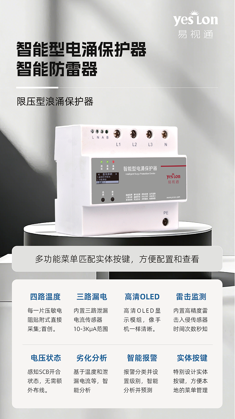
FSS Smart Surge Protective Device
Integrated smart SPD with built-in monitoring and communication, LCD/OLED display, combined lightning protection and status monitoring.
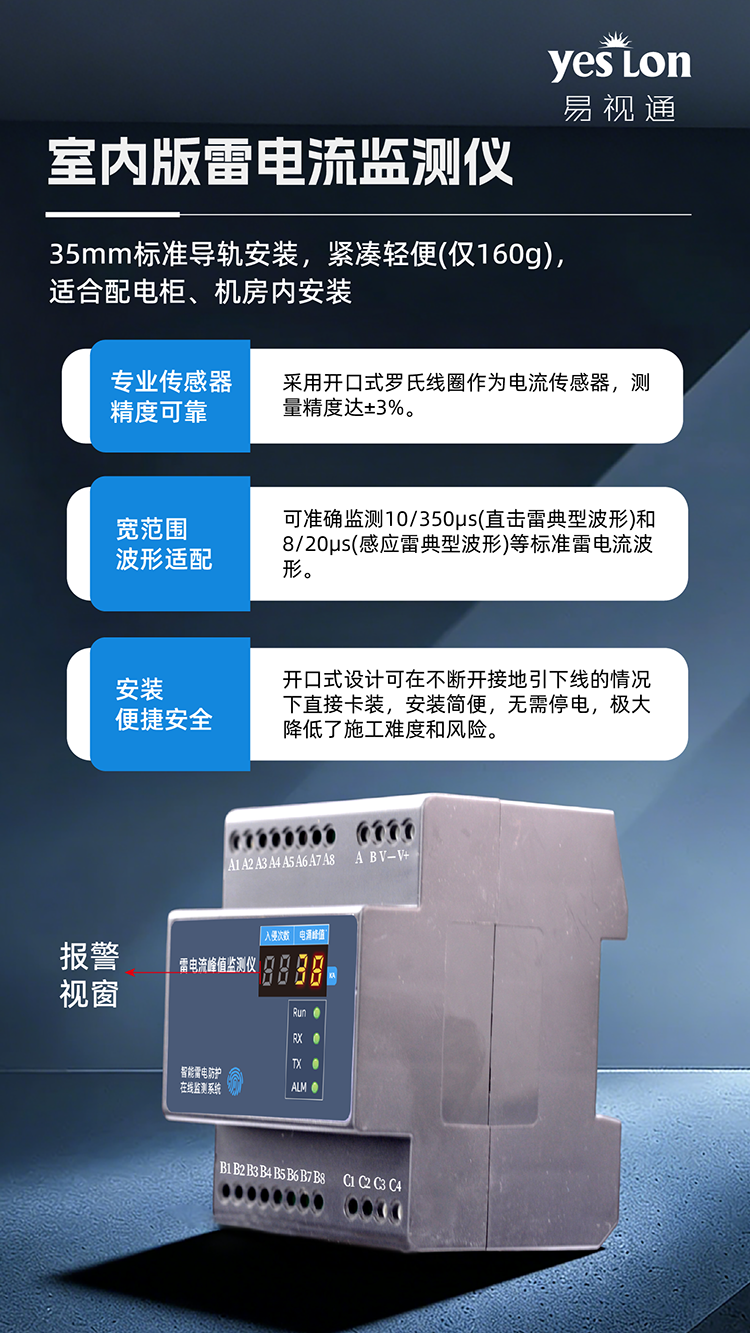
FL Lightning-Current Monitor
Peak lightning current 0.1-200kA measurement, GPS/BeiDou timing, IP67 outdoor protection, precise lightning-event attribution.
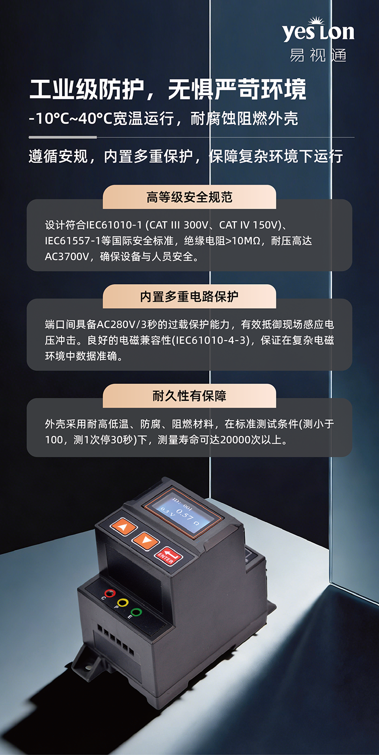
FR Ground-Resistance Detector
Three-pole ground-resistance online monitoring, 0.1-200 Ohm range, real-time sensing of grounding-system status, ensuring effective lightning protection.
Learn MoreFS Lightning-Protection Monitor Application Scenarios
Contact us for detailed solutions, quotes and technical support.