
FL Lightning-Current Monitor
FL Series
Peak lightning current 0.1-200kA measurement, GPS/BeiDou timing, IP67 outdoor protection, precise lightning-event attribution.
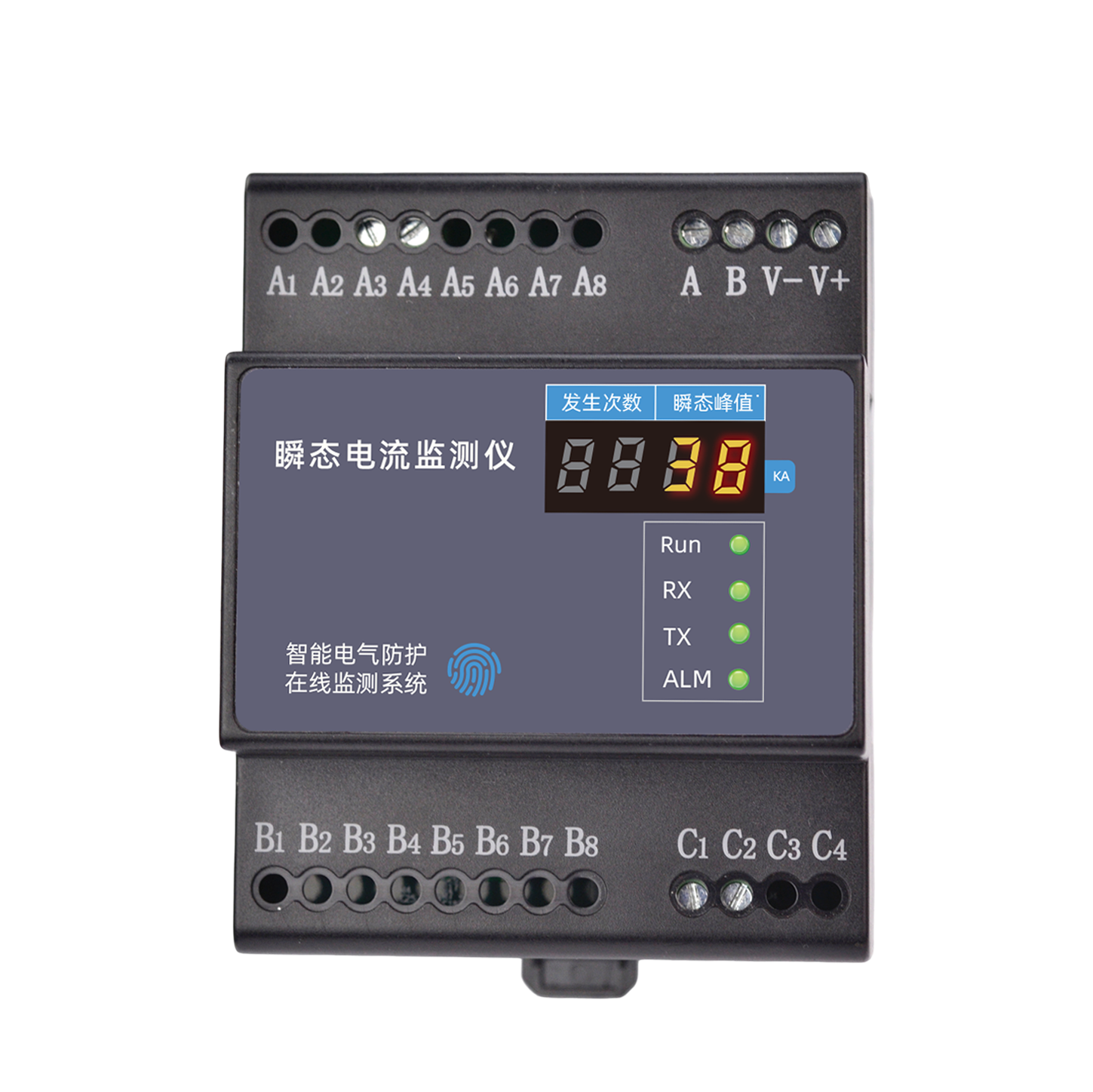
Product Overview
The FL transient current monitor integrates measurement, control, transmission and intelligence, featuring fast response, fast computation, high event counts, multiple waveform types and high acquisition accuracy. With a high-precision Rogowski coil and digital integrator algorithm, it ensures high-speed, accurate data. It is widely used in equipment lifecycle management, arc fault/arcing monitoring, external overvoltage monitoring, electrical safety hazard monitoring in high/low-voltage distribution cabinets, predictive maintenance of load motors and other scenarios, serving industries such as military, petrochemical, construction, railway, port, airport and new energy.
Core capabilities
Fast response: 1μS (microsecond) instantaneous acquisition, fast computation completed in 1ms (millisecond). Over 60 overvoltage monitoring events can be completed in one 1S cycle, supporting acquisition of multiple overvoltage waveform types. Acquisition accuracy up to ±3%, with customizable ranges of 0.1kA-10kA and 1kA-100kA. Dedicated one-to-one high-agility Rogowski coil with zero-flux, high shielding and simulation-based design. Product Features
Data Generated
Product Features
Fast
Fast response: 1μS (microsecond) instantaneous acquisition (1/1,000,000 s); fast computation: completed in 1ms (millisecond) (1/1000 s).
More
More events: over 60 overvoltage monitoring events per 1S cycle; more types: supports acquisition of multiple overvoltage waveform types.
High standards
High acquisition accuracy: up to ±3%; customizable acquisition ranges: 0.1kA-10kA, 1kA-100kA; complete type coverage: multi-group, multi-type waveform peak detection.
High-precision Rogowski coil
High-precision Rogowski coil with digital integrator algorithm; the dedicated one-to-one high-agility Rogowski coil with zero-flux, high shielding and simulation-based design, combined with the digital integrator, ensures high-speed, accurate data.
All-weather sensor
The split-core flexible Rogowski coil operates stably under strong electromagnetic interference, adapting to complex industrial on-site environments.
Wide range of uses
Equipment lifecycle management, arc fault/arcing monitoring, external overvoltage monitoring, electrical safety hazard monitoring in high/low-voltage distribution cabinets, and predictive maintenance of load motors. Selection Guide
System Topology
Selection Guide
Model naming convention
FL - 0 1 1 1 2 - R FL Product: Transient current monitor 0 Signal acquisition range: 0=1kA-120kA; 1=0.1kA-1kA 1 Signal channels: 1=single current channel; 2=dual current channels 1 Channels: 1=single current channel 1 Function: 1=peak; 2=peak+energy; 3=waveform; 4=waveform+energy 2 Mounting method: 1=outdoor; 2=indoor R Communication: R=RS485; E=Ethernet; Z=ZigBee; G=GPRS Model Installation environment Function RS485 Zigbee Ethernet MQTT FL-11122-R Indoor version Peak Supported --- --- --- FL-11122-Z Indoor version Peak --- Supported --- --- FL-11122-E Indoor version Peak --- --- Supported Supported Technical Parameters
| Model | Installation environment / Function / RS485 / Zigbee / Ethernet / MQTT |
| FL-11122-R | Indoor version / Peak / Supported / --- / --- / --- |
| FL-11122-Z | Indoor version / Peak / --- / Supported / --- / --- |
| FL-11122-E | Indoor version / Peak / --- / --- / Supported / Supported |
Technical Parameters
Basic parameters (indoor version)
Operating voltage AC 220V±20% Power consumption 2W Operating temperature -20℃~60℃ Operating humidity <95% Weight 160g Dimensions 72*90*69mm (L×W×H) Housing material Thermoplastic material UL94V0 Protection rating IP20 Mounting method Standard 35mm DIN rail mounting
| Operating voltage | AC 220V±20% |
| Power consumption | 2W |
| Operating temperature | -20℃~60℃ |
| Operating humidity | <95% |
| Weight | 160g |
| Dimensions | 72*90*69mm (L×W×H) |
| Housing material | Thermoplastic material UL94V0 |
| Protection rating | IP20 |
| Mounting method | Standard 35mm DIN rail mounting |
Smart monitoring functions
Communication RS485/Zigbee/Ethernet Communication protocol Modbus/MQTT protocol Transient current High-frequency pulse, multi-wave characteristics Acquisition range 50A~5kA (customizable) Acquisition accuracy ±3% Data storage 100 records, auto-overwrite Polarity Positive/negative Occurrence time Year.Month.Day.Hour.Minute.Second Installation Instructions
| Communication | RS485/Zigbee/Ethernet |
| Communication protocol | Modbus/MQTT protocol |
| Transient current | High-frequency pulse, multi-wave characteristics |
| Acquisition range | 50A~5kA (customizable) |
| Acquisition accuracy | ±3% |
| Data storage | 100 records, auto-overwrite |
| Polarity | Positive/negative |
| Occurrence time | Year.Month.Day.Hour.Minute.Second |
Installation Instructions
a
Installation dimension drawing
72mm length 90mm width 69mm height 35mm standard DIN rail b
Sensor description
Sensor specifications Sensor type Rogowski coil Design features Zero flux, high shielding, simulation-based design Structure Split-core flexible Rogowski coil Anti-interference capability Stable operation under strong electromagnetic interference Algorithm Digital integrator Accuracy assurance Dedicated one-to-one high-agility design c
| Sensor type | Rogowski coil |
| Design features | Zero flux, high shielding, simulation-based design |
| Structure | Split-core flexible Rogowski coil |
| Anti-interference capability | Stable operation under strong electromagnetic interference |
| Algorithm | Digital integrator |
| Accuracy assurance | Dedicated one-to-one high-agility design |
Interface description
Interface definition No. Definition 1 V+, V-: 5V DC power input (not needed when 220V supply is present) 2 A, B: RS485 bus interface 3 A3, A4: 220V AC power input, A3-live, A4-neutral 4 C1, C2: C1-Rogowski coil core wire, C2-Rogowski coil shield wire 5 Antenna port: for wireless communication, the antenna port is on the bottom of the module 6 Ethernet port: for Ethernet communication, the Ethernet port is on the top of the module
| No. | Definition |
| 1 | V+, V-: 5V DC power input (not needed when 220V supply is present) |
| 2 | A, B: RS485 bus interface |
| 3 | A3, A4: 220V AC power input, A3-live, A4-neutral |
| 4 | C1, C2: C1-Rogowski coil core wire, C2-Rogowski coil shield wire |
| 5 | Antenna port: for wireless communication, the antenna port is on the bottom of the module |
| 6 | Ethernet port: for Ethernet communication, the Ethernet port is on the top of the module |
Key Points
Definition: The FL transient current monitor is a FEXLINK device for online monitoring of lightning current and transient overcurrent, recording surge invasion waveforms and peaks. Core capabilities: high-bandwidth sampling captures transient current waveforms and records peak, polarity and timestamp, supporting lightning strike event tracing and statistical analysis. Applicable scenarios: lightning protection project acceptance, lightning strike event tracing, SPD effectiveness evaluation and similar scenarios. Related products: FSS intelligent surge protective device, outdoor lightning current monitor, ESX intelligent edge computing gateway.
FAQ
Related Products
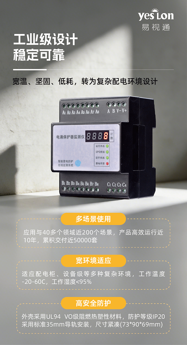
FS Lightning-Protection Monitor
SPD online monitoring, microamp-accuracy leakage-current detection, supporting four/five-element and nine-element monitoring, full visibility of SPD status and life trend.
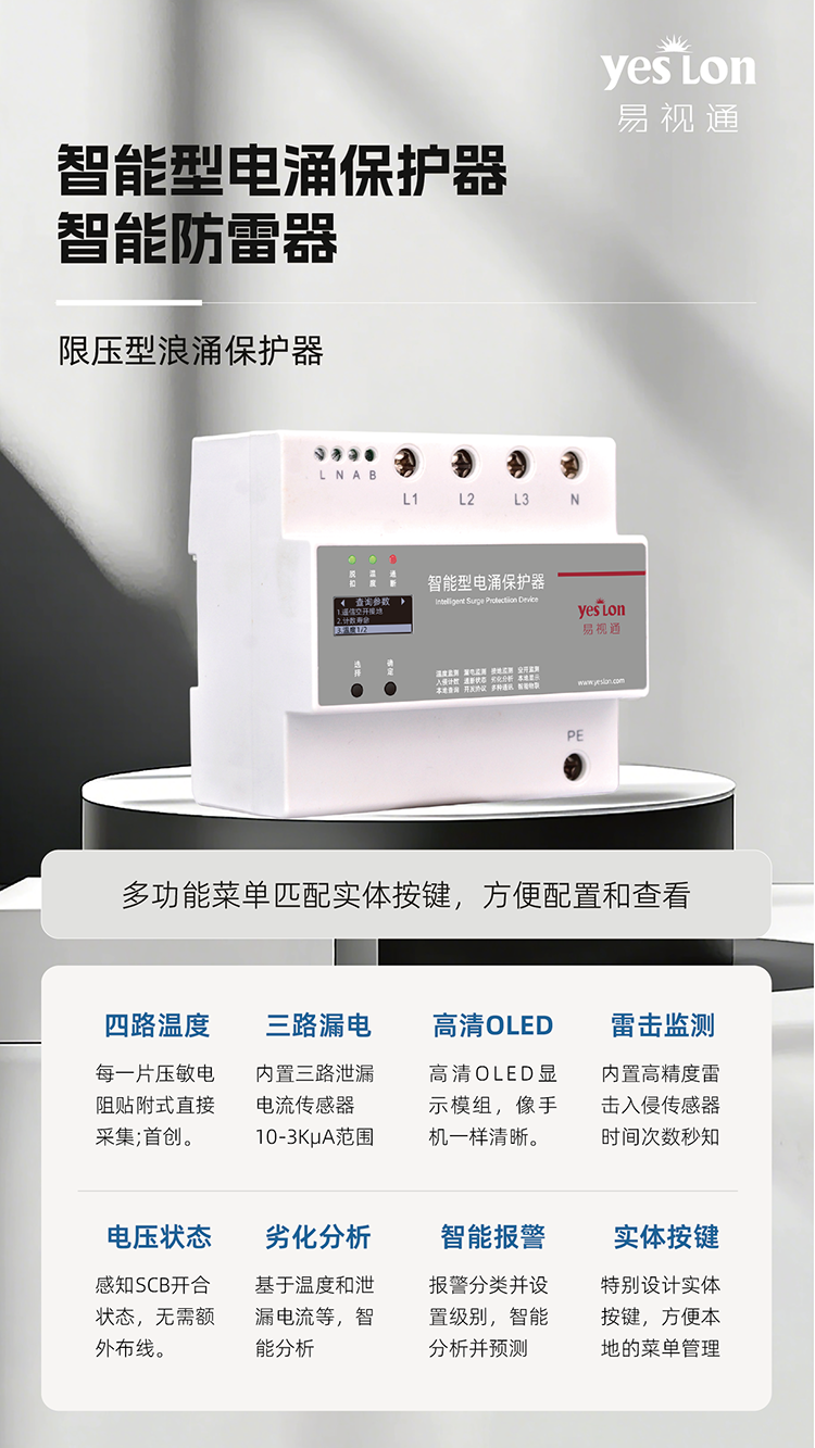
FSS Smart Surge Protective Device
Integrated smart SPD with built-in monitoring and communication, LCD/OLED display, combined lightning protection and status monitoring.
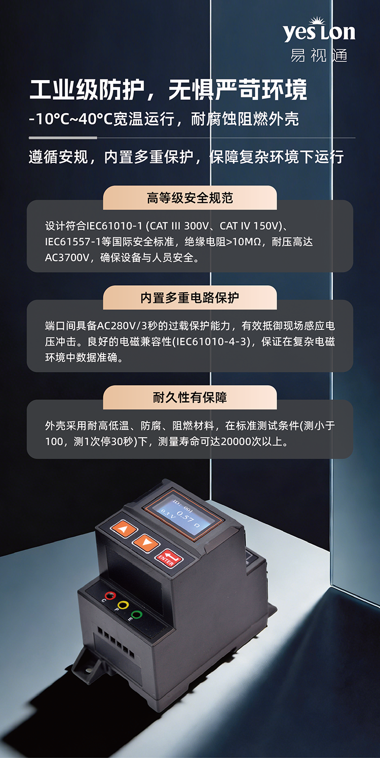
FR Ground-Resistance Detector
Three-pole ground-resistance online monitoring, 0.1-200 Ohm range, real-time sensing of grounding-system status, ensuring effective lightning protection.
Learn MoreFL Lightning-Current Monitor Application Scenarios
Contact us for detailed solutions, quotes and technical support.