
Direct answer
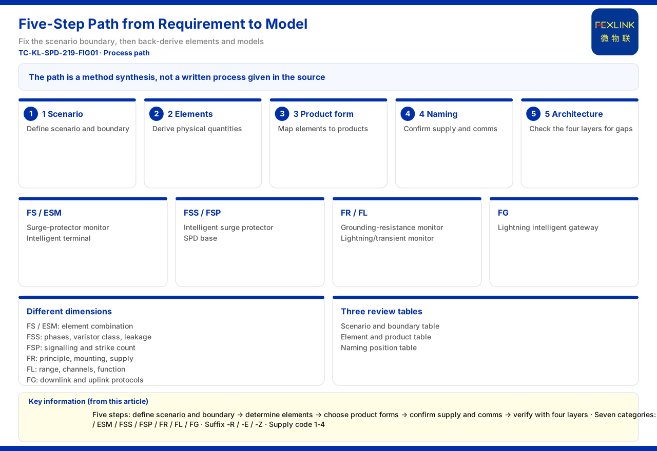
From requirement to model, lightning-protection monitoring selection can be summarised in five steps: define the scenario and system boundary, determine the monitoring elements, choose the product form, confirm the naming digits such as supply and communication, and finally use the system architecture to verify end-to-end completeness. The product material does not present this set of steps as a process chapter, but it separately provides the product-line panorama, the model rules of each product family, the contrast between scenarios and recommended combinations, and the four-layer system architecture. Stringing these existing pieces together in order yields a selection path usable for scheme review. It should be stressed that this path is a method induction, not a written flow given in the product material itself.
1. First frame the scenario and system boundary
The first step of selection is not to look at models but to state clearly for whom, for what, and where the boundary lies. The product material gives its basis as a contrast between scenarios and recommended product combinations, where the lightning-protection rows include online grounding-grid monitoring for substations and traction substations, oil-tank-area and petrochemical lightning-protection and explosion-proof, and surge protective device status monitoring (retrofit of existing SPDs). Classify the project into a similar scenario first, then clarify whether the monitoring object is an entire grounding grid, a single oil-tank area, or the status of an existing surge protective device, and the boundary becomes clear. Once the system boundary is fixed, the subsequent elements and products unfold around that scope and do not lose focus as the device list grows longer.
2. Derive monitoring elements from the scenario
Once the boundary is fixed, the second step is to derive from the scenario which physical quantities need monitoring. The product-line panorama in the product material lists intelligent lightning protection as seven categories, providing a product-side basis for the element mapping: the FS surge protective device monitor, the ESM intelligent lightning-protection monitoring terminal, the FSS intelligent surge protective device, the FSP SPD lightning-protection base, the FR grounding resistance monitor, the FL lightning current / transient current monitor and the FG lightning-protection smart gateway. Each category corresponds to different elements; for example a grounding-related scenario needs grounding-resistance collection capability and a lightning-current-related scenario needs lightning-current monitoring capability. At this point the alarm requirement should also be revisited: if the project requires safety red-line-level alarms, and the grounding item among the safety red-lines is based on GB 50057, the grounding element is a mandatory coverage item and cannot be left optional.
3. Map elements to product form
The third step is to map elements to specific product forms, noting that the same element may be carried by different products. The dimension descriptions of the model rules given by the product material show that families differ in their selection dimensions: the FS and ESM use monitoring-element combinations, the FSS uses phase count, varistor class and leakage current, the FSP uses base remote signalling and lightning-strike counting, the FR uses detection principle, installation method and supply, the FL uses detection range, channel count and function, and the FG uses downlink and uplink protocols. This means selection is not the same question asked of every category but a separate confirmation by each category's own dimensions. Taking grounding as an example, the FR grounding resistance monitor (e.g. FR-01311-R) requires confirmation of detection principle, installation and supply; taking sensing extension as an example, the FSP SPD lightning-protection base (e.g. FSP-21100-R) requires confirmation of whether remote signalling and lightning-strike counting meet the need.
4. Confirm naming digits: model, supply and communication
The fourth step returns to the model itself for digit-by-digit confirmation. The general suffixes given by the product material are -R (RS485), -E (Ethernet) and -Z (Zigbee), with 4G reserved and optional on some products; the supply mode codes for lightning-protection products are 1 (DC12V), 2 (AC220V), 3 (solar) and 4 (lithium battery). Selection must translate the element conclusions into model digits: the communication suffix must agree with on-site wiring and platform access, the supply digit with the on-site power conditions, and the installation digit with the indoor or outdoor environment. Taking the FS surge protective device monitor (e.g. FS-00011-R) as an example, its supply is DC12V and it offers several communication variants; taking the FL lightning current / transient current monitor (e.g. FL-01222-R) as an example, the detection range and function tier must also be confirmed. Confirming digit by digit turns a vague roughly the same model into an item-by-item checklist.
5. Use the four-layer architecture to verify end-to-end completeness
The fifth step is an overall check. The product material summarises the monitoring system as perception layer, edge layer, platform layer and application layer, in which the perception-layer monitoring modules ascend through a gateway into the platform. Placing the selection result back into these four layers can check whether a break exists: whether the perception layer covers all elements, whether the edge-layer gateway downlink matches the device suffixes and its uplink matches the platform, and whether the platform layer has the corresponding access method. If any layer is missing, for example devices without a gateway, or a gateway downlink inconsistent with the device suffixes, the scheme looks complete on paper but cannot form an end-to-end link in practice. This step needs no new material; it merely uses the architecture diagram to review the conclusions of the previous four steps.
6. Write the selection conclusion as three reviewable tables
To give the review something to hold on to, the selection conclusion can be arranged as three tables. The first is a scenario and boundary table, recording which scenario the project falls into and the scope of the monitoring object. The second is an element and product table, listing row by row the required element, the carrying product name and model, and the material basis hit. The third is a naming-digit check table, filling in the digits corresponding to communication, supply, installation, detection range and other dimensions. The three tables need not be complex; the key is to let the reviewer see why it was chosen rather than only that it was chosen. For the client, the second table is especially important: it binds each model to a specific element, avoiding a list that looks complete but actually misses an item. The scenario contrast, model rules and suffixes, and supply codes in the product material can be used directly as the basis for filling in the tables, and the filling process itself is a review of the conclusions of the previous four steps.
7. The material gives no written flow
The boundary should be made clear: the product material does not provide an explicit process chapter, step numbering or decision tree named risk identification, system boundary, monitoring elements and product mapping. The five steps here are a method organised from the existing information of the product-line panorama, model rules, scenario contrast and four-layer architecture, and are not the original text of the product material. Selection can use this order as a discussion framework, but it must not be claimed as the only process specified by the material, nor may decision rules absent from the material be invented from it.
Scope and limitations
First, this article explains only the organising order of the selection decision; the factual boundary is limited to the product material, and no parameter, standard or certification not listed there is introduced.
Second, the product line, model dimensions, scenario contrast and naming rules here are as recorded in the product material; this article does not infer the specifications of unlisted models from them.
Third, the product material gives no written selection flow; the five steps here are a method induction from the listed facts and do not represent a standard process given by the material.
Fourth, the selection of a specific project must be determined in conjunction with the on-site boundary, alarm requirement, supply and communication, and platform requirements; this article provides no scheme design or selection calculation.


