
Direct answer
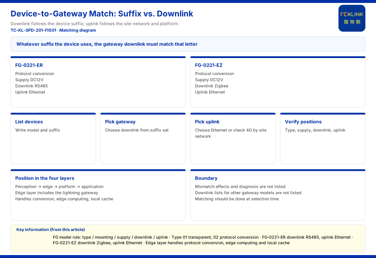
Matching a device to a gateway is essentially lining up the device's communication suffix with the gateway's downlink mode. The FG lightning-protection smart gateway (e.g. FG-0221-ER) given by the product material marks both a downlink and an uplink segment in the model: the FG-0221-ER is protocol conversion, DC12V, with RS485 downlink and Ethernet uplink; the FG-0221-EZ is protocol conversion, DC12V, with Zigbee downlink and Ethernet uplink. The general device suffixes are -R for RS485, -Z for Zigbee and -E for Ethernet, so the gateway downlink must agree with the device suffix. A matching error often only surfaces at the networking or commissioning stage; selection should align the two segments up front to avoid data that cannot be sent up at the edge layer.
1. A gateway model carries both a downlink and an uplink segment
The product material gives the model rule of the FG lightning-protection smart gateway as an ordered sequence of gateway type, installation method, supply, downlink and uplink, where gateway type 01 means transparent transmission and 02 means protocol conversion. Taking the FG-0221-ER as an example, 02 means protocol conversion, the downlink digit is R (RS485) and the uplink digit is E (Ethernet); the FG-0221-EZ is likewise protocol conversion but with a downlink digit of Z (Zigbee), and its uplink is also Ethernet. That is, the same gateway series can adapt to different device interfaces by changing the downlink digit. Selection should first confirm whether transparent transmission or protocol conversion is needed, then confirm the letter segments of the downlink and uplink; the information expressed by the model already contains the matching relationship.
2. The device suffix and the gateway downlink must line up one to one
The first matching rule is direct: whatever suffix the device has, the gateway downlink should choose the corresponding letter. In the product material, the suffix of the FS surge protective device monitor (e.g. FS-00011-R) indicates its communication method, the FR grounding resistance monitor offers -R, -Z and -E variants, and the FL lightning current monitor likewise offers three communication options. If the device is -R, the gateway downlink should be RS485; if the device is -Z, the gateway downlink should be Zigbee. Note here that the device suffix and the downlink protocol are not judged by the letter's appearance alone but correspond to the definitions given by the product material: -R is RS485 (Modbus), -Z is Zigbee (Modbus), and -E is Ethernet (MQTT). Only by comparing the definitions with the model will the uplink and downlink not be reversed.
3. The uplink method decides which network it connects to
Once the downlink is fixed, look at the uplink. In the communication protocol matrix given by the product material, the device uplink includes Modbus TCP and MQTT (Ethernet, 4G), plus optional IEC 61850 at gateway level. The uplinks of the FG-0221-ER and the FG-0221-EZ are both Ethernet, which shows they suit sites with a wired network; if the site has only a wireless network, the availability of 4G should be checked among the uplink methods listed in the protocol matrix, and it must not be assumed that any gateway can use 4G. A further distinction is that IEC 61850 is an optional item at gateway level, usually for cases where the upper system requires that protocol; without such a requirement, Modbus TCP or MQTT already meets most access needs. Note that the uplink choice and the downlink choice are two independent matters: the downlink is decided by the device suffix, and the uplink by the on-site network and platform requirements, and one letter cannot summarise both at once. Confirming the uplink separately avoids the hidden gap of a matching downlink but an impassable uplink.
4. The gateway's position in the four-layer architecture
Understanding the matching relationship also requires knowing which layer the gateway occupies. The product material summarises the monitoring system as perception layer, edge layer, platform layer and application layer; the edge layer contains the lightning-protection smart gateway, the intelligent edge-computing gateway and the industrial gateway, and undertakes protocol conversion, edge computing and local buffering. This means the gateway's role is not merely to connect wires but to convert the different device downlink protocols and send them uplink. Because the conversion happens at the edge layer, the device suffix and the gateway downlink must appear as a pair; otherwise the data is already broken before it enters the edge layer. Remembering this layer position explains why the gateway model marks both downlink and uplink, and why the matching check must be completed at the selection stage.
5. An actionable order for the matching check
Casting the matching into actions can follow four steps. Step one lists the devices: write out each device's product name, model and communication suffix, and mark its corresponding protocol. Step two fixes the gateway: choose the gateway downlink from the set of device suffixes, judge whether RS485 and Zigbee must both be supported, and if so choose a corresponding model or set up separate gateways. Step three fixes the uplink: choose Ethernet or check 4G availability according to the on-site network conditions, and confirm the uplink protocol the platform accepts. Step four checks the naming digits: break the gateway model apart digit by digit and confirm that the gateway type, supply, downlink and uplink agree with the conclusions above. Since the product material also codes supply and installation method, they should be confirmed at the same time to avoid checking the protocol but not the supply. These four steps introduce no new material; they merely use the existing model rules and protocol matrix side by side so that the matching conclusion can be reviewed item by item.
6. Matching under existing and mixed devices
In a retrofit, the site often contains devices with several suffixes at once. The product material shows that the FS and FR both have -R, -Z and -E variants and the FL models also offer three communication options; if the existing devices are mainly RS485 while the new devices are Zigbee, the gateway downlink must cover both interfaces or gateways must be configured separately. Because the downlink digit given by the FG series is a single letter, such a mixed scenario needs an arrangement in the number or hierarchy of gateways, rather than expecting one single model to support two downlinks at once. Likewise, if the existing gateway uplink is already fixed to Ethernet, the uplink of a new gateway should preferably remain consistent to avoid a second uplink path at the edge layer that adds O&M complexity. The product material gives no specific scheme for mixed networking, and the relevant arrangement should be based on on-site conditions and the existing device list.
7. Consequence of mismatch not given in the material
The boundary should be made clear: the product material does not give the consequence of a mismatch between the gateway downlink protocol and the device communication suffix, nor a diagnostic method, nor a downlink protocol list for gateway models other than the FG. One must therefore not infer from the product material what happens on a mismatch, how to troubleshoot it, or whether other gateways are compatible. Selection should concentrate on matching up front, that is, confirming before ordering that the device suffix and the gateway downlink agree; as for diagnosis and handling at the networking stage, these are subject to the manuals of the devices actually used and on-site commissioning.
Scope and limitations
First, this article explains only the matching method between device protocols and gateway models; the factual boundary is limited to the product material, and no parameter, standard or certification not listed there is introduced.
Second, the gateway model rules, suffix definitions and protocol matrix here are as recorded in the product material; this article does not infer the downlink protocol of unlisted models from them.
Third, the product material does not give the consequence and diagnosis of a mismatch; the matching order here is a method induction from the listed facts and does not represent a decision rule given by the material.
Fourth, the gateway selection of a specific project must be determined in conjunction with on-site network conditions, the device list and platform access requirements; this article provides no networking design or selection calculation.


