
Direct Answer
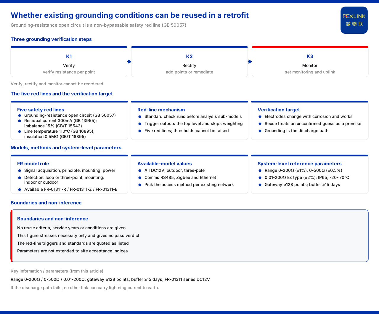
The grounding conditions of an old lightning-protection system cannot be carried over without verification. The product knowledge base lists "abnormal open circuit of grounding resistance" as one of the safety red-lines that cannot be bypassed, with GB 50057 as the basis, and states that there are five such red-lines and that no one can raise the thresholds. Since a grounding abnormality is a bottom-line criterion for system safety, the grounding must be verified before a retrofit to confirm whether it is still intact and whether it meets the discharge requirement; it cannot be assumed valid merely because "it has always been in use". Grounding is the discharge channel of lightning protection, and once the channel fails, no amount of good work elsewhere can safely lead the lightning current into the earth.
1. Why Grounding Cannot Be Reused by Default
In an existing-installation retrofit, grounding is often treated as "foundation work completed long ago" and excluded from the verification scope. But the grounding body is buried underground, its state changes with soil corrosion, construction disturbance and nearby development, and it gives no automatic feedback when running. The reason an old system appears to have "never had a problem" may simply be that it has not yet met a lightning event severe enough to expose the problem, which does not mean the grounding conditions remain acceptable. Treating grounding as usable by default in effect carries an unconfirmed assumption into the retrofit scheme as a premise; once the premise fails, the subsequent protection configuration, monitoring parameters and alarm logic all rest on a wrong foundation. Verifying grounding is therefore not an optional step but a precondition of the retrofit.
2. Why the Safety Red-Line Mechanism Cannot Be Bypassed
The product knowledge base expresses the bottom line through a front-end interception mechanism: standard verification runs before the analysis sub-models are computed, and once a red-line is triggered, the highest-level alarm is output directly and all weighted computation is skipped. The purpose of this mechanism is to ensure that the national-standard bottom line is not diluted by a composite score. Under it, a grounding abnormality is not an ordinary item that "may be offset by other high scores after weighting" but an event that must be answered unconditionally no matter how good the other indicators are. The product knowledge base also states that there are five red-lines and they cannot be bypassed, and that no one can raise the thresholds. For a retrofit project this means the result of grounding verification has no room for accommodation: unqualified is unqualified, and the criterion cannot be lowered for schedule or cost reasons.
3. One of the Five Safety Red-Lines Points Directly at Grounding
The five safety red-lines listed by the product knowledge base cover the basic safety dimensions of residual current, grounding, three-phase voltage imbalance, line temperature and insulation resistance. The one directly corresponding to grounding is the abnormal open circuit of grounding resistance, with GB 50057 as the basis. The other four are residual current reaching 300mA (based on GB 13955), three-phase voltage imbalance exceeding 15% (based on GB/T 15543), line temperature reaching 110°C (based on GB 16895) and insulation resistance below 0.5MΩ (based on GB/T 16895). Seen together, these entries show that the red-lines cover the bottom-line conditions most likely to endanger personal and equipment safety directly, and grounding is the only one specifically aimed at the discharge channel, which explains why grounding must be verified separately in a retrofit.
4. Which Quantities to Check When Verifying Grounding
Verification does not look only at "whether a grounding body exists" but at whether the grounding resistance is within an acceptable range. The model rule given by the product knowledge base for the grounding resistance monitor combines signal acquisition, detection principle, installation method and power supply, where the detection principle distinguishes the loop method from the three-pole method and the installation method distinguishes outdoor from indoor. The in-sale grounding resistance monitor (FR-01311-R) is DC12V, outdoor and three-pole; its variants FR-01311-Z and FR-01311-E differ only in communicating over Zigbee and Ethernet, while the base model uses RS485. The three-pole method suits the measurement of a conventional independent grounding body, while the distinction between the loop method and the three-pole method corresponds to different site conditions. Only by first selecting the measurement method according to site conditions can comparable grounding-resistance results be obtained before the retrofit.
5. The System-Level Basis Measures the Whole Ground Grid
Grounding monitoring is often not a single-point action but continued observation of a whole ground grid. The system-level reference parameters given by the product knowledge base for the grounding-resistance monitoring system are: monitoring-unit ranges selectable as 0-200Ω (standard type, ±1%), 0-500Ω (high-precision type, ±0.5%) and 0.01-200Ω explosion-proof type (±2%); protection rating IP65 and operating temperature -20 to 70°C; the intelligent gateway mounts at least 128 points and can be cascaded, with data caching of at least 15 days. These parameters show that the object of grounding monitoring is a system rather than a single instrument: the range determines the applicable scenario, the gateway mounting capacity determines how many measurement points can be covered, and the data cache determines whether data is retained when the network is down. Only on this basis can a retrofit scheme judge how many measurement points an old ground grid needs.
6. Grounding Is Already a Routine Perception Item
It is worth noting that grounding is not a special topic newly added by intelligent monitoring but a routine item of the existing perception system. The product knowledge base records that the grounding item among the basic vital signs is used to identify TN, TT and IT system types, showing that grounding status already has a place in routine parameter-level perception. Bringing grounding into routine perception means it can both take part in daily trend observation and trigger red-line interception when it exceeds a limit, combining the roles of "usable in normal times" and "always upheld at the bottom line". For grounding verification this provides a reasonable position: verification does not add a burden to the retrofit but puts back into the monitoring scope an item that should have been observed continuously all along.
7. The Landing Combination in a Typical Scenario
In its typical application scenarios and selection comparison, the product knowledge base lists the recommended combination for "online monitoring of substation/traction-substation ground grids" as the grounding resistance monitor (1 set per point), the lightning-protection smart gateway and the cloud platform. Two features of this combination are worth noting: first, "1 set per point", showing that ground-grid monitoring is configured per measurement point and the number of points is determined by the scale of the grid; second, "gateway plus platform", showing that monitoring data must travel through the gateway to form continued observation. Accordingly, the complete action of old-grounding verification should be: first verify the existing grounding resistance by point, then decide from the result whether additional points or rectification are needed, and finally configure the monitoring and upload channel. The order of verification, rectification and monitoring must not be reversed.
Scope of Application and Limitations
First, this article only explains why the grounding conditions of an old lightning-protection system must be verified; the factual boundary is the product knowledge base, and no standard clauses, parameters, certifications or cases not listed there are introduced.
Second, the product knowledge base gives no verification criterion, reuse age or reuse condition for whether old grounding can be carried over directly; this article only stresses the necessity of verification and gives no qualified conclusion.
Third, the trigger conditions and basis standards of the five safety red-lines, and the model rule, in-sale models, supply, installation method and communication of the grounding resistance monitor, are cited from the source.
Fourth, the range, accuracy, protection rating, operating temperature, gateway mounting and cache parameters of the grounding-resistance monitoring system are cited from the source; this article does not extrapolate them into acceptance indicators for any site.
Fifth, a specific retrofit project must verify the grounding verification and rectification scheme against the site soil conditions, grid scale and measurement conditions; this article provides no selection, measurement or construction calculation.


