
Direct Answer
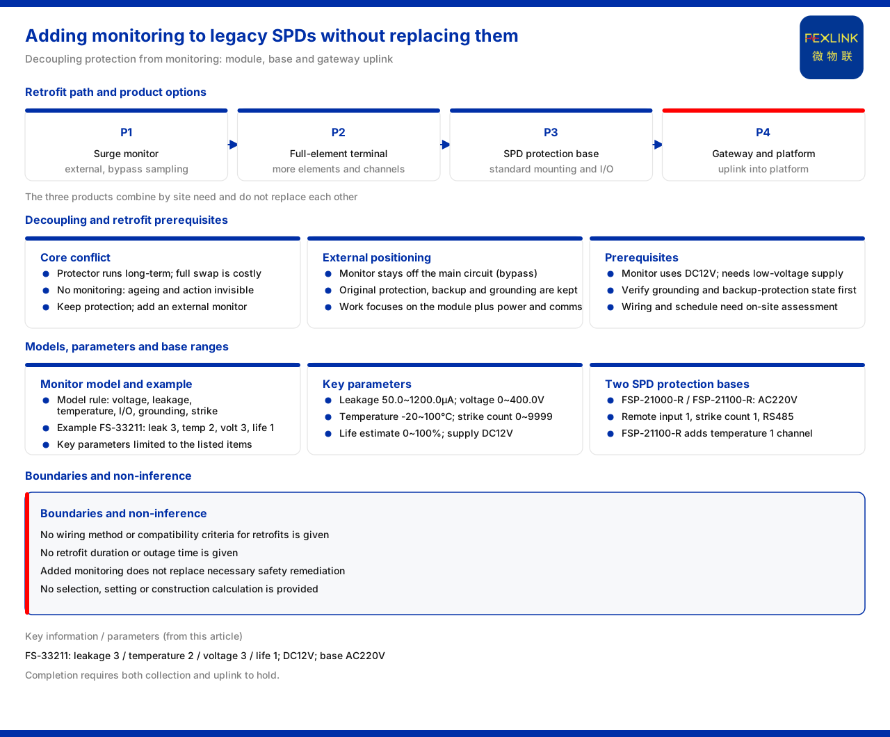
To achieve status monitoring on existing SPDs, it is not necessary to remove and replace the protective devices already in service. The product knowledge base lists "SPD status monitoring (existing SPD retrofit)" as a typical scenario, with a recommended combination of the surge protective device monitor, the all-parameter lightning-protection monitoring terminal and the SPD lightning-protection base; the surge protective device monitor is positioned as a monitoring module external to the monitored SPD and does not itself perform a protection function. In other words, adding monitoring means adding a layer of status collection outside the existing SPD, not replacing the protective body. Whether this is feasible depends on whether suitable collection points and an installation landing point can be found.
1. The Core Conflict in an Existing-Installation Scenario
The difficulty of an existing installation is that the protective device is already installed and has been running for a long time, so replacing the body brings a string of actions such as power interruption, dismantling and rewiring, with high cost and risk. If it is not monitored at all, however, whether the device has aged, whether the backup protection has operated, and whether the grounding is abnormal can still only be found by periodic inspection or after failure. The essence of this conflict is that "protection" and "monitoring" have been bound to the same device. The product knowledge base offers another way to split them: the protective body stays in place to perform the discharge function, while the monitoring function is carried by an external module; the two are physically separate and connected in data. In this way, the retrofit target changes from "replacing the protective device" to "adding monitoring points".
2. External Monitoring Decouples Two Layers of Responsibility
The product knowledge base positions the surge protective device monitor as "surge protective device monitor (lightning-protection monitoring module)", a monitoring module external to the monitored SPD. This positioning is crucial: it shows that the monitor does not enter the main protection circuit but observes the state of the protective device by bypass sampling. For an existing-installation retrofit, decoupling the responsibilities means the original protection configuration, backup protection specification and grounding method can all be retained, and the retrofit actions concentrate on adding the monitoring module together with its power supply and communication. The solution provider can tell the owner not "a batch of protective devices must be replaced" but "without changing the protective body, states that were previously invisible are made visible online", and the two have completely different retrofit costs and implementation windows. For operation and maintenance, the difference is practical: replacing the body often has to be entered into a maintenance plan and coordinated with a power outage, whereas adding monitoring can be done within an existing maintenance window, making the retrofit schedule easier to match to production.
3. What the Monitor Collects
The concrete capability of the external monitoring module is defined by the surge protective device monitor. The product knowledge base gives its model rule, composed of voltage channel count, leakage-current channel count, temperature channel count, switch quantity, grounding and lightning, with communication listed separately; the example model FS-33211 contains 3 leakage-current channels, 2 temperature channels, 3 voltage channels and 1 life estimate. The key parameters are leakage current 50.0 to 1200.0μA (±10μA), voltage 0 to 400.0V (±0.1V), temperature -20 to 100°C (±1°C), lightning strike count 0 to 9999 counts (minimum trigger 0.1kA) and life estimate 0 to 100%, all supplied at DC12V. For an add-on scenario, a DC12V supply means the monitoring module needs a separate low-voltage power source and wiring, which should be reserved in the retrofit scheme in advance.
4. The All-Parameter Terminal Is Another Placement
If the existing site has many protection points, or a more complete set of parameters must be covered at once, an all-parameter monitoring terminal can be used. The product knowledge base records that the model rule of the intelligent lightning-protection monitoring terminal combines power supply, display, phase number, current parameter, board version and communication; the board version is divided into a basic four-element version and a flagship multi-element version, the power supply supports DC5V or AC220V, and the communication is RS485. Compared with single-point external monitoring, it is more flexible in power supply and the multi-element version can cover several parameters in one device. Which placement to choose mainly depends on how concentrated the protection points are and what power supply conditions can be provided: when points are scattered, single-point external modules are preferred; when points are concentrated and centralised power can be provided, the all-parameter terminal is easier to manage uniformly.
5. The Base Provides an Installation Point without Changing the Body
An existing-installation retrofit has another practical problem: where the monitoring module should be mounted. The product knowledge base records that the SPD lightning-protection base includes the FSP-21000-R and FSP-21100-R, both with AC220V supply, digital display, remote signalling input 1, lightning strike count 1 and RS485; the FSP-21100-R adds temperature monitoring 1, while the FSP-21000-R has no temperature. The value of the base is that it provides a standardised collection and installation position for remote signalling, lightning strike count and temperature, so that the protective body can gain status-upload capability without modification. For existing points where only operation and temperature need to be observed, without the full power-path parameters, the base is often the least invasive way to add monitoring.
6. Only the Combination Forms a Complete Path
The three products do not replace one another but are combined according to site needs. The recommended combination of the product knowledge base places the surge protective device monitor, the all-parameter lightning-protection monitoring terminal and the SPD lightning-protection base side by side, showing that an existing-installation retrofit can be chosen along two dimensions, parameter coverage and installation landing point: use the monitor when a complete set of power-path parameters is needed, the all-parameter terminal when many parameters are to be collected centrally, and the base when a standardised installation position and basic remote signalling are needed. After the combination is complete, check again whether the parameters cover all four segments and whether the data can travel through the gateway into the platform. Only when both collection and upload hold is the add-on monitoring truly complete, rather than a data source installed without producing operation-and-maintenance value.
7. Boundaries That Must Be Verified Before Installation
It should be noted that adding monitoring does not mean the original system can skip verification. The product knowledge base does not list the wiring method for adding monitoring to an existing SPD, the compatibility and adaptation criteria with the original SPD, or the retrofit duration or power-outage time. Therefore the wiring scheme, the compatibility judgement and the implementation window must all be verified separately against the actual site and cannot be inferred directly from the product knowledge base. In particular, the grounding conditions and the backup protection state should be verified before deciding the add-on method; if a hidden hazard already exists on site, adding monitoring alone cannot replace the necessary rectification. Doing this step first makes the add-on scheme rest on a real foundation.
Scope of Application and Limitations
First, this article only explains the product path for adding monitoring to an existing SPD; the factual boundary is the product knowledge base, and no standard clauses, parameters, certifications or cases not listed there are introduced.
Second, the product knowledge base gives no wiring method, compatibility and adaptation criteria, retrofit duration or power-outage time for adding monitoring to an existing SPD; these must be verified against the site and are not inferred here.
Third, the external positioning, model rule and key parameters of the surge protective device monitor, and the model rule, board versions and power-supply basis of the all-parameter lightning-protection monitoring terminal, are limited to the source entries.
Fourth, the supply, display, remote signalling input, lightning strike count, temperature and communication of the two SPD lightning-protection base models are cited from the source; this article does not infer the configuration of unlisted models.
Fifth, a specific retrofit scheme must be verified against the site protection configuration, power-supply conditions and grounding conditions; this article provides no selection, setting or construction calculation.


