
How Grounding Monitoring Data Reaches the Platform
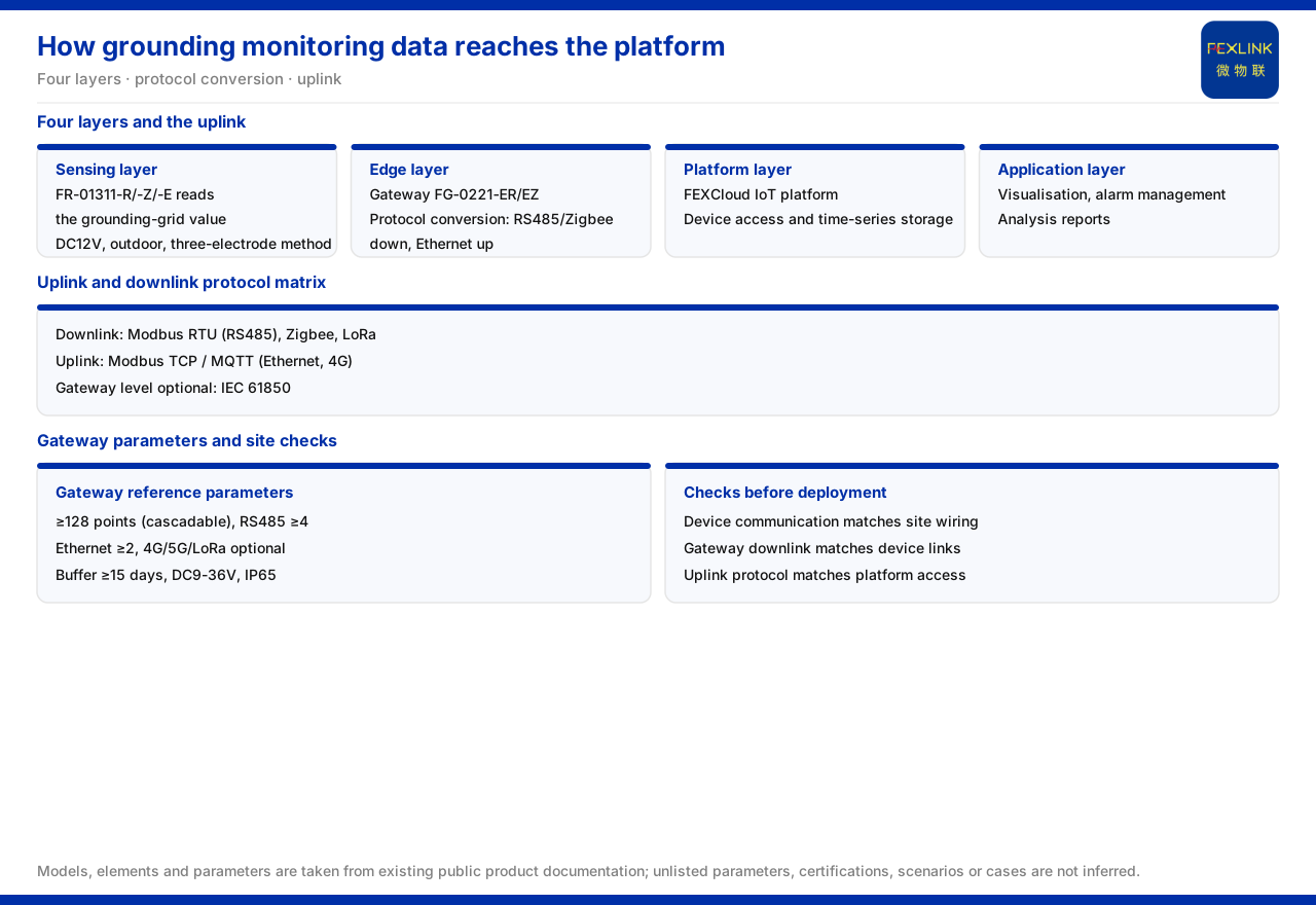
Direct answer: the upload path for grounding monitoring data is determined by the four-layer architecture of the monitoring system. The grounding resistance monitor sits at the perception layer, collecting signals such as the ground-grid resistance. The data is converted by edge-layer devices such as the lightning-protection smart gateway and sent upward by the uplink protocol to the platform layer, the FEXCloud IoT cloud platform. After device access and time-series storage, the application layer presents the results as visualization, alarms, and reports. For the grounding resistance monitor (FR series, for example FR-01311-R), communication is selectable as RS485, Zigbee, or Ethernet; which one is chosen depends on which downlink the gateway uses. Stringing together "device communication — gateway conversion — uplink protocol — platform access" gives the complete chain from field to platform.
Starting at the Perception Layer: What the Grounding Resistance Monitor Collects
At the front of the chain is the grounding resistance monitor. The documented model rule is FR–[signal acquisition][detection principle][mounting][power]–[communication], where signal acquisition 01 means ground-grid resistance; detection principle 2 is the loop method and 3 is the three-point method; mounting 1 is outdoor and 2 is indoor.
Taking the models in service as examples, the grounding resistance monitor (FR series), for example FR-01311-R (RS485), FR-01311-Z (Zigbee), and FR-01311-E (Ethernet), are all DC12V powered, outdoor-mounted, and use three-point measurement. The same monitoring capability can thus be realized through three communication methods: RS485 or Ethernet for wired, and Zigbee for wireless. The first segment of the upload path is choosing the communication method that matches the site wiring conditions.
Protocol Conversion: What the Lightning-Protection Gateway Does
The raw signal collected by the monitor usually does not go directly to the platform; it first passes through an edge-layer device for protocol conversion and data aggregation. The lightning-protection smart gateway (FG series) plays this role: the lightning-protection smart gateway (FG series), for example FG-0221-ER (RS485 downlink, Ethernet uplink) and FG-0221-EZ (Zigbee downlink, Ethernet uplink), is DC12V powered, with the difference mainly in the downlink. Whether field devices are wired RS485 or wireless Zigbee determines whether the ER or EZ version is chosen; the uplink is uniformly Ethernet.
This is the key link in grounding data upload: the monitor is responsible for "acquiring it," and the gateway for "forwarding it." If the monitor uses RS485, the gateway downlink should also use RS485; if the monitor uses Zigbee, the gateway downlink should also use Zigbee. If uplink and downlink do not match, data cannot enter the gateway, let alone reach the platform.
The Uplink and Downlink Protocol Matrix
At the protocol level, the documented communication matrix runs along two lines. The device downlink uses Modbus RTU (running over RS485), Zigbee (Modbus), or LoRa; the device uplink uses Modbus TCP or MQTT (running over Ethernet or 4G), and at the gateway level IEC 61850 is optional.
Matching this matrix to grounding monitoring yields a clear path: the grounding resistance monitor uses RS485, Zigbee, or Ethernet; the data is aggregated to the gateway by Modbus RTU or Zigbee; the gateway then uploads to the platform by Modbus TCP or MQTT, and when interconnection with a substation automation system is required, the gateway-level IEC 61850 can be used. The same grounding data may therefore pass through three stages from field to platform — downlink protocol, protocol conversion, and uplink protocol — and each stage's protocol must connect with the next.
Platform Layer and Application Layer
After the data reaches the platform layer, the FEXCloud IoT cloud platform continues the processing. The documented platform-layer capabilities include device access, a time-series database, and an AI inference engine; the application layer then provides web and app visualization, alarm management, analysis reports, and mobile inspection.
For grassroots monitoring data this means upload is not an endpoint but an entry point: once ground-grid resistance enters the platform, it can be stored as a time series and compared for trends; when a value exceeds a limit, an alarm is triggered; and it can form part of reports and inspection records. "How grounding monitoring data reaches the platform" is therefore really asking how to bring grounding data into this complete flow from access to application.
How Gateway Reference Parameters Affect Upload Capability
Viewed at the system level, the documentation also gives reference parameters for the grounding resistance monitoring system's smart gateway: mounting of no fewer than 128 points with cascading, no fewer than 4 RS485 ports, no fewer than 2 Ethernet ports, optional 4G/5G/LoRa, data buffering of no fewer than 15 days, wide-voltage DC9-36V supply, and IP65 protection.
These parameters directly affect upload design. The mounting point count decides how many monitoring points one gateway can carry, and cascading decides how it expands; the RS485 and Ethernet port counts decide wired access capacity; optional 4G/5G/LoRa means a network can be formed and uploaded even where fixed networks are absent; no fewer than 15 days of buffering means data can be held during a network interruption and re-sent after recovery; and wide-voltage supply and IP65 relate to the gateway's adaptability in distribution or outdoor environments. Whether grounding data uploads stably depends not only on protocol matching but also on whether the gateway's access capacity, buffering, and supply conditions are usable on site.
Upload Chains in Typical Applications
The documentation records that the FR/FRP series grounding resistance monitors have been applied to online monitoring of railway traction substation ground grids and to the Jinzhou Port oil-tank area (10 units per tank). These applications share one feature: monitoring points are distributed in different locations and their grounding data must be aggregated to a unified platform.
In such a scenario the upload chain usually appears as follows: the grounding resistance monitors at each monitoring point connect to a nearby gateway, which performs protocol conversion and data buffering, and then uploads via Ethernet or 4G to the platform. Where monitoring points are numerous, the gateway's cascading and large mounting count matter; where network conditions are limited, wireless methods and data buffering become the key to keeping data from being lost.
Questions to Confirm Before Implementation
To make grounding data upload reliably, the following questions should be confirmed at the planning stage:
1. The communication method chosen for each grounding monitoring point: RS485, Zigbee, or Ethernet. 2. Whether the gateway version aggregating that point corresponds to the monitor's communication method — that is, whether the downlink matches. 3. Whether the gateway's uplink is available: Ethernet or a wireless method such as 4G. 4. Whether the gateway's uplink protocol agrees with the platform side: Modbus TCP or MQTT, and whether gateway-level IEC 61850 is enabled for a substation automation system. 5. Whether the gateway's access capacity, buffering days, and supply conditions meet the site's point count and installation environment.
These questions correspond to the four segments of the upload chain: acquisition, conversion, uplink, and access. A mismatch in any segment means the data cannot reach the platform completely.
Summary
Grounding monitoring data upload can be summarized as: the grounding resistance monitor collects data at the perception layer using RS485, Zigbee, or Ethernet; the lightning-protection smart gateway completes protocol conversion and aggregation at the edge layer, matching the monitor on the downlink and sending data to the platform on the uplink by Modbus TCP, MQTT, or optional gateway-level IEC 61850; the FEXCloud IoT cloud platform completes device access and time-series storage at the platform layer; the application layer presents results through visualization, alarms, reports, and mobile inspection. The gateway's mounting count, RS485 and Ethernet port counts, buffering days, supply, and protection rating determine whether this chain can carry the site's monitoring scale stably. Checking the four segments one by one yields an actionable upload path for grounding data.


