
Mapping Graded Protection to Monitoring Points
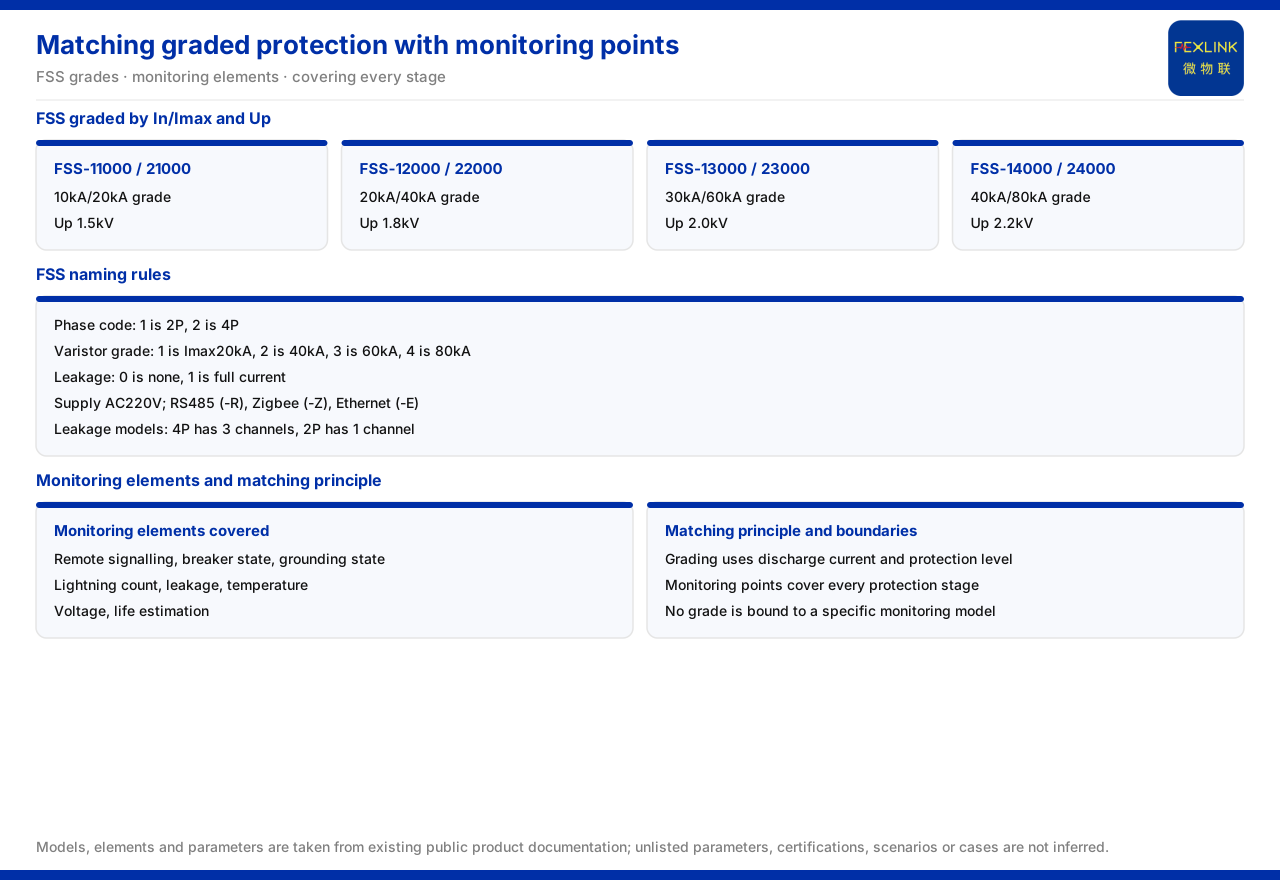
Direct answer: graded protection answers "at which stage the energy is released and to what level the residual voltage is limited," while monitoring placement answers "whether each protector is still in an effective state." The correspondence principle is: grading configures stages by discharge current and voltage protection level, and monitoring points should cover the condition of every protector so that failure of any link in the chain can be discovered. The documentation confirms the discharge-current and voltage-protection-level bands of the intelligent surge protective device (FSS series), the pole counts and leakage options of each band, and the monitoring elements covered by the surge protective device monitor and the intelligent lightning-protection monitoring terminal. It does not bind a particular band to a particular monitoring model, so the correspondence should rest on "cover every stage" rather than on automatic model pairing.
What Graded Protection Actually Grades
The core of graded protection is to release lightning or surge energy in layers and to limit the residual voltage after each stage to a level the downstream equipment can withstand. The documentation gives the bands of the intelligent surge protective device by two parameters: nominal discharge current In and maximum discharge current Imax, which describe the protector's ability to release energy; and voltage protection level Up, which describes the voltage ceiling the protected equipment experiences after the protector operates.
The specific bands of the intelligent surge protective device (FSS series) can be read band by band. The lowest band is represented by FSS-11000, with FSS-21000 in the same band, offering 10kA/20kA and a voltage protection level of 1.5kV. The second band is represented by FSS-12000, with FSS-22000, offering 20kA/40kA and 1.8kV. The third band is represented by FSS-13000, with FSS-23000, offering 30kA/60kA and 2.0kV. The highest band is represented by FSS-14000, with FSS-24000, offering 40kA/80kA and 2.2kV.
These bands show that a higher energy-release capability corresponds to a higher voltage protection level. This is exactly the problem graded protection must handle: the stage near the power incoming line carries a larger discharge current, while the stage closer to the terminal equipment emphasizes holding residual voltage down. Grading is therefore not simply connecting protectors in series, but configuring protectors of different capability on the principle that the front stage releases energy and the rear stage limits voltage.
Why Monitoring Must Cover Every Stage
A characteristic of the graded protection chain is that an abnormal condition in any one protector weakens the protection capability of the entire link. If the front protector has degraded from repeated operations, more energy passes to the rear; if the rear protector has failed, terminal equipment is directly exposed to residual voltage beyond its tolerance. Protector degradation often has no obvious external feature, and visual inspection can hardly tell whether it is still effective.
This is why monitoring point placement and graded protection must correspond: grading decides how many lines of defense exist, and monitoring decides whether each line is online. If points are placed at only one stage, the status of the other stages is a blind spot; only when every stage has corresponding status acquisition can "one link has failed" be turned from invisible into visible. In other words, the goal of monitoring placement is not to pile up quantity but to have every line of defense in the graded chain covered.
Which Elements the Monitoring Devices Cover
At different stages, the monitoring means available differ. By model, the surge protective device monitor can collect remote signalling, switch status, grounding status, lightning strike count, leakage, temperature, voltage, and life estimation; this means it can reflect not only whether the protector has operated but also whether its supply and operating environment are normal. Where more complete SPD monitoring is required, the intelligent lightning-protection monitoring terminal is positioned as a full-element SPD monitor; its models carry information on power, display, phase count, current parameters, and version type, and offer both a basic four-element version and a flagship multi-element version.
Comparing these two monitoring means with graded protection yields a practical placement approach: where a stage's protector must be judged for operation, grounding, leakage, or temperature anomaly, use the surge protective device monitor; where more comprehensive element acquisition for the SPD is required, use the intelligent lightning-protection monitoring terminal. The documentation gives monitoring elements and model composition but does not prescribe which stage "must" use which monitoring model; the model-to-stage correspondence still has to be determined with the system structure.
A Method for Matching Stages to Monitoring Points
Combining the bands with the monitoring elements, the correspondence can be completed as follows:
First, list the protection stages from the system structure — for example the incoming, distribution, and terminal stages. The stage division is the basis of placement; without clear stages it is impossible to judge which points need coverage.
Second, match protection capability to each stage using the discharge-current and voltage-protection-level bands. The stage nearer the incoming line, carrying a larger discharge current, takes a higher capability band; the stage nearer the terminal, emphasizing voltage limiting, is chosen together with the withstand level of the protected equipment.
Third, configure status monitoring for each stage so that operation, grounding, leakage, temperature, and life are visible. For stages with higher monitoring requirements, use the more comprehensive monitoring terminal.
Fourth, handle the voltage-level difference at the terminal. The Class D power SPDs in the documentation are divided by voltage level into YSE DM-D220, YSE DM-D48, YSE DM-D24, and YSE DM-D12, corresponding to 220V, 48V, 24V, and 12V. Choose the model matching the terminal supply level and bring the terminal stage into the monitoring scope so that it does not become a blind spot.
How Communication and Data Aggregation Affect Placement
Monitoring placement must consider not only "where to install" but also "how the data gets out." The intelligent surge protective device series is powered at AC220V, with communication selectable as RS485 (suffix -R), Zigbee (suffix -Z), or Ethernet (suffix -E). A single monitoring scheme can therefore choose wired or wireless according to site conditions, or choose an Ethernet uplink according to data volume and management approach.
In addition, the channel count of residual-current versions directly affects how many leakage monitoring points one device can cover: the 4P type has 3 channels and the 2P type has 1 channel. When a stage must monitor several leakage points at once, the channel count is a parameter that must be checked before placement; if channels are insufficient, more devices must be added or the placement adjusted.
On system landing, the typical application scenarios include "protector status monitoring (existing SPD retrofit)," whose recommended combination includes the surge protective device monitor, full-element SPD monitoring, and the SPD lightning-protection base, and "oil-tank farm / petrochemical lightning protection," whose recommended combination includes protector monitoring. These give a recommended combination direction; how many points each stage needs and which communication to use still depend on the site structure.
Boundaries to Make Explicit
What the documentation confirms is: the intelligent surge protective device is divided into four bands by discharge current and voltage protection level and can combine phase count, varistor level, and leakage; the pole counts, leakage channels, and communication methods of each band are listed; and the elements the monitoring devices can cover are clearly listed. What the documentation does not prescribe is which monitoring model a given protection stage "must" correspond to, nor the number and location of points at each stage. These are design decisions that depend on the system structure, the importance of the protected equipment, and site conditions.
Separating the "confirmable correspondence" from the "to-be-designed correspondence" is the landing point. Bands and monitoring elements are the factual basis, covering every stage is the placement principle, and the specific model and quantity are the design result.
Implementation Recommendations
1. Draw the protection stages first, making clear which stages participate in energy release and voltage limiting, to form the skeleton of placement. 2. Select a protection capability band for each stage by discharge current and voltage protection level. 3. Configure status monitoring for each stage so that operation, grounding, leakage, temperature, and life can be acquired. 4. Match the terminal to the Class D power SPD by supply voltage level and bring terminal monitoring into scope. 5. Choose RS485, Zigbee, or Ethernet by site conditions, and check whether the residual-current version's channel count meets placement needs. 6. Refer to the recommended combinations of typical scenarios to set the plan direction, without equating a recommended combination with each stage's specific model.
Summary
Graded protection answers "how many lines of defense there are," and monitoring placement answers "whether each line is online." The four protection-capability bands, the monitoring element list, the communication methods, and the typical scenarios provide a usable starting point; but "which monitoring model and how many points per stage" still has to be designed. Holding to the principle that every stage is covered builds a clear, checkable correspondence between grading and placement.


