Direct answer
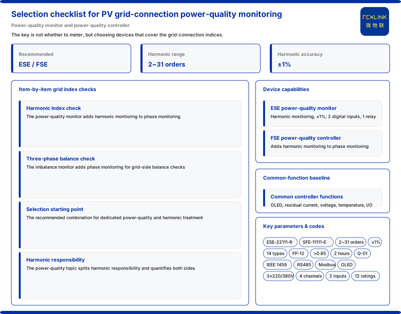
For power-quality monitoring of grid-connected photovoltaic systems, the key is not "whether to install a meter" but choosing the class of equipment that covers the grid-connection assessment indicators. In its typical application scenarios and selection comparison, the product knowledge base gives the recommended combination for "power quality/harmonic targeted governance" as the ESE power-quality monitor (ESE-22111-R) and the FSE multi-parameter electrical intelligent controller (power-quality type) (SFE-11111-R), configured with the Tianyan engine harmonic analysis. Based on the wording listed in the product knowledge base, this article explains which grid-connection indicators each part of this combination covers, what the shared functions provide as a baseline, how three-phase balance and harmonic responsibility are checked, and how to turn selection into an item-by-item checklist; it does not infer the grid-connection conclusion of any specific plant.
1. Why photovoltaic grid connection looks at power quality first
The concerns of photovoltaic grid connection differ from ordinary distribution. An inverter converts DC to AC and inherently carries high-order harmonics at the switching frequency and its multiples; the grid-connection side also requires voltage deviation, harmonics and three-phase imbalance to fall within allowed ranges. "Whether grid connection is qualified" is therefore not a single-value judgement but a combination across several power-quality dimensions. The product knowledge base lists "power quality/harmonic targeted governance" as a separate scenario, precisely indicating that its core is power quality rather than simple energy metering.
The starting point of selection should therefore be "first measure voltage, current, harmonics and phase fully", and only then consider metering and reporting. The power-quality monitor and the power-quality controller are listed as this scenario's recommended combination precisely because they cover the two grid-connection quantities of phase and harmonics, and both can serve on site as the basis for verifying grid-connection indicators.
2. The selection starting point given by the scenario comparison
The scenario comparison maps "power quality/harmonic targeted governance" to the combination of the power-quality monitor and the power-quality controller, and notes the configuration of the Tianyan engine harmonic analysis. This gives a "combination" rather than a "single device": one is a standalone monitor, the other a controller that also has control capability, and the two differ in installation and integration.
It should be noted that the scenario comparison provides a starting point, not an end point. The recommended combination shows that this class of scenario usually needs equipment with phase and harmonic monitoring capability, but whether a particular grid-connection point should use a monitor or a controller, how many current specifications, and which networking method still depend on the number of field circuits and the networking conditions. This article therefore sets out the two device classes' capability boundaries for selection verification.
3. Capability of the power-quality monitor
The product knowledge base states that the power-quality monitor adds harmonic monitoring to phase monitoring, covering the 2nd to 31st harmonics with an accuracy of ±1%; it also has 2 digital inputs and 1 relay output, with RS485 (Modbus) communication. This set of parameters can be read from three angles.
In measurement dimension, phase monitoring corresponds to three-phase imbalance and phase relationships, and harmonic monitoring corresponds to the 2nd-to-31st spectral decomposition; together they form the verification surface of grid-connection power quality. In accuracy, ±1% gives harmonic measurement a definite accuracy wording rather than a vague "measurable". In interfaces, the digital inputs can connect external states, the relay output can drive interlocking, and RS485 (Modbus) shows it faces standard industrial networking. The product knowledge base therefore lists it as equipment that can support verification of grid-connection harmonic indicators.
4. The power-quality controller and shared functions
The product knowledge base states that the FSE multi-parameter electrical intelligent controller (power-quality type) likewise adds harmonic monitoring to phase monitoring, corresponding to the model range SFE-11111 to 11161-E/G, covering 12 current specifications and 2 networking methods. The two figures matter: 12 current specifications mean the same model can match circuits of different capacities, and 2 networking methods mean the access form can be chosen according to site network conditions. Compared with the standalone monitor, the controller's positioning is "monitoring plus control", suitable for circuits needing local interlocking.
The product knowledge base also states that the multi-parameter electrical intelligent controller in its meter type (SFA-10011-E/G), three-phase balance type (SFB-11011-E/G) and power-quality type (SFE-11111-R) share common functions: OLED display, residual current 1 channel, voltage 3×220/380V, temperature monitoring 4 channels, 2 digital inputs, 2 relay outputs, meter monitoring, and two RS485 channels (Modbus). This common base provides a baseline for checking grid-connection monitoring capability — the same controller platform shares basic capabilities across the three types, with the differences concentrated in phase and harmonics. In selection, one can first confirm whether the platform meets the circuit's basic needs, then decide from the differences whether phase or harmonics are required.
5. Three-phase balance verification on the grid-connection side
Grid connection looks not only at harmonics but also at whether the three phases are balanced. The product knowledge base states that the ESB three-phase imbalance monitor (ESB-22111-R) shares the architecture of the ESA all-parameter smart meter, corresponding to the model range ESB-22111 to 22161-R, with voltage 3×220/380V, an OLED display and RS485 communication, adding phase monitoring to three-phase monitoring, and is suitable for verifying three-phase balance on the grid-connection side. This means "same architecture" is the premise: it shares basic measurement capability with the all-parameter smart meter, and the difference is the added phase monitoring, which directly observes three-phase imbalance.
The capability boundary must be distinguished. The product knowledge base states that this device adds phase monitoring but does not say it includes harmonic monitoring; harmonic verification should be undertaken by the power-quality monitor or the power-quality controller. In a grid-connection scenario, three-phase balance and harmonic verification therefore often need to be paired: use the three-phase imbalance monitor to verify balance, and use the two device classes with harmonic monitoring capability to verify spectral indicators.
6. Harmonic responsibility allocation and pollution-source location
Grid-connection harmonic treatment cannot avoid two questions: how harmonic responsibility is divided between the user side and the grid side, and who produces the harmonics. The product knowledge base states that block Q (power quality) of the Tianyan engine includes harmonic responsibility allocation, based on IEEE 1459, used to quantify the user-side and grid-side harmonic contributions. This provides an analysis basis for grid-connection harmonic responsibility: the division is not simply looking at total harmonics, but quantifying contributions by side.
In the locating step, the product knowledge base states that the harmonic fingerprint library contains 14 classes of device fingerprints, including the photovoltaic-inverter fingerprint FP-12, with the system matching by cosine similarity greater than 0.85 and locking the pollution source within 2 hours. For photovoltaic grid connection, this capability points directly at the judgement "whether the inverter is a harmonic source". Combining responsibility allocation with fingerprint location gives a traceable path: measure harmonics first, then locate the source, then divide responsibility, and only then discuss a treatment scheme.
7. Turning selection into a verifiable checklist
First, confirm the scenario belongs to "power quality/harmonic targeted governance" and configure equipment as a combination. Second, for circuits needing standalone harmonic verification, choose the power-quality monitor (ESE-22111-R), checking the 2nd to 31st harmonics, ±1% accuracy, 2 digital inputs, 1 relay output and RS485 (Modbus). Third, for circuits needing monitoring plus interlocking, choose the power-quality controller, checking the SFE-11111 to 11161 model range, 12 current specifications and 2 networking methods. Fourth, for grid-connection points needing three-phase balance verification, add the three-phase imbalance monitor (ESB-22111-R). Fifth, confirm the platform shared functions (OLED, residual current 1 channel, 3×220/380V, temperature 4 channels, 2 digital inputs, 2 relay outputs, meter monitoring, two RS485 channels) meet the basic needs. Sixth, confirm whether harmonic responsibility allocation (IEEE 1459) and the Tianyan engine harmonic analysis are included in the scheme.
Scope and limitations
First, this article only restates wording listed in the product knowledge base, and its factual boundary is limited to the scenario comparison's recommended combination for "power quality/harmonic targeted governance", the parameters of the power-quality monitor and the power-quality controller, the three controller types' shared functions, the ESB three-phase imbalance monitor (ESB-22111-R), block Q of the Tianyan engine (IEEE 1459), and the harmonic fingerprint library (14 device fingerprint classes, cosine similarity greater than 0.85, 2-hour locking).
Second, this article does not infer the power-quality monitor's metering capabilities beyond phase and harmonics, nor infer that the three-phase imbalance monitor includes harmonic monitoring.
Third, whether grid-connection indicators are qualified should follow on-site measured data, local grid-connection requirements and the relevant standards; the device capabilities listed here are the product knowledge base's wording and do not constitute a commitment to any specific plant's grid-connection conclusion.
Fourth, the final selection of model range, current specification and networking method is an engineering design judgement; this article gives only the wording for item-by-item verification and does not replace project design and approval.