
Direct answer
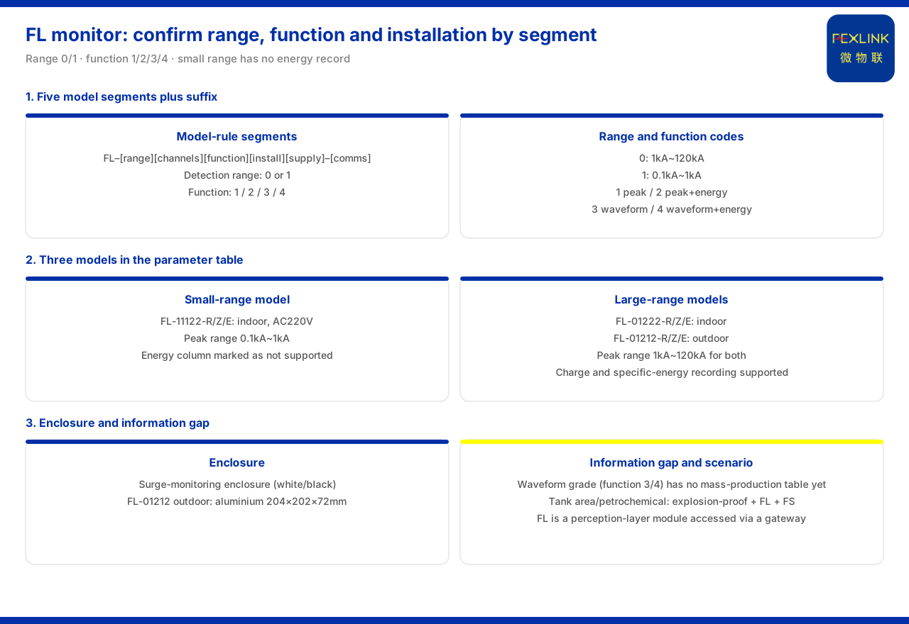
The key to selecting a lightning-current or transient-current monitor is to confirm the model segment by segment according to the model rules rather than guessing from the model's appearance. The product knowledge base gives the model rules of the FL lightning-current / transient-current monitor as five segments — detection range, channel count, function, installation method and supply — followed by a communication suffix. Detection-range code 0 corresponds to 1 kiloampere to 120 kiloamperes and code 1 to 0.1 kiloampere to 1 kiloampere; function code 1 denotes peak, 2 denotes peak plus energy, 3 denotes waveform and 4 denotes waveform plus energy. According to the parameter table, the small-range lightning-current / transient-current monitor (FL-11122-R/Z/E) is indoor-mounted, AC220V-supplied, with a peak range of 0.1 kiloampere to 1 kiloampere, and its energy column is marked as unsupported; the large-range lightning-current / transient-current monitor (FL-01222-R/Z/E) is the indoor version and (FL-01212-R/Z/E) is the outdoor version, both with a peak range of 1 kiloampere to 120 kiloamperes and both supporting energy recording of charge quantity and unit energy, supplied at AC220V with communication optionally R, Z or E. It should be noted that models with the waveform function (function positions 3 and 4) do not yet have a mass-production selection table. In selection, first fix the range by the lightning-current magnitude under test, then the function, installation and communication.
1. Model rules: five segments plus a communication suffix
Reading the model rules is the starting point of selection. The rules given by the product knowledge base split the model into five segments: detection range, channel count, function, installation method and supply, followed by a communication suffix. Within one series, the first five segments determine what the monitor measures, how many channels it measures, what it records, where it is installed and how it is supplied, while the suffix determines how it communicates. Once this rule is grasped, the model is no longer a meaningless string but a digit-by-digit configuration statement. Any model encountered in selection can be checked segment by segment against the five segments and the suffix to confirm whether it matches the site requirement.
2. Range steps: 1 to 120 kiloamperes and 0.1 to 1 kiloampere
The detection-range code has two steps. The product knowledge base records that code 0 corresponds to 1 kiloampere to 120 kiloamperes and code 1 corresponds to 0.1 kiloampere to 1 kiloampere. The two cover different current magnitudes: one addresses larger lightning and transient currents, the other smaller currents. In selection, first estimate the magnitude of lightning or transient current that may occur on the circuit under test, decide on step 0 or step 1 accordingly, and then continue configuring among the models of that step. A wrong range will cause a large range to measure small signals inaccurately, or a small range to fail to cover a large current.
3. Function position: peak and energy
The function code determines which data the monitor records. The product knowledge base gives four function codes: 1 denotes peak, 2 denotes peak plus energy, 3 denotes waveform and 4 denotes waveform plus energy. The basic function is peak recording; adding energy means that, besides the peak, charge quantity and unit energy are also recorded; the waveform step records the waveform, and the waveform-plus-energy step records both waveform and energy. The later the function position, the richer the recorded information and the higher the demand on data volume and back-end processing. In selection, judge by the site need: if it is enough to know whether a lightning strike occurred and its amplitude, peak suffices; if the lightning energy is also to be assessed, choose a function position with energy.
4. Installation and form: indoor and outdoor versions
Installation method is one segment of the model. The product knowledge base records that the lightning-current / transient-current monitor has a lightning-protection monitoring enclosure in white and black; the outdoor version FL-01212 is an aluminium enclosure with dimensions of 204 by 202 by 72 millimetres, while the small-range FL-11122 is the indoor version. Combined with the parameter table, the large-range FL-01222 is also the indoor version. Under the same range step, therefore, indoor and outdoor correspond to different models: the outdoor version uses an aluminium enclosure to suit the outdoor environment, while the indoor version is used in panels or indoor situations. In selection, first fix indoor or outdoor by installation position, then check whether the enclosure and dimensions meet the on-site space.
5. Communication suffix: three options, R, Z and E
Communication is indicated by the suffix, with three options, R, Z and E. The product knowledge base gives R, Z and E as options in the communication column of the three lightning current monitor entries FL-11122, FL-01222 and FL-01212. Once detection range, channel count, function, installation and supply are fixed, communication is relatively independent and can be chosen by the type of gateway or bus connected on site. The suffix should be matched to the interface of the on-site aggregation equipment to ensure the monitor can connect smoothly into the edge layer.
6. Not yet in mass production: the waveform information gap
One information gap must be flagged. The known information gaps of the product knowledge base record that models with the waveform function do not yet have a mass-production selection table. This means that the FL models corresponding to function position 3 (waveform) and function position 4 (waveform plus energy) currently have no mass-production parameters to consult; although the model rules list these two function codes, when it comes to a specific model and supply, the mass-production selection table should govern. If the site genuinely requires waveform recording, the available model should be confirmed with the supply side first, and an order should not be placed on the rule code alone.
7. Application position: the perception layer and petrochemical scenarios
In terms of system position, the lightning-current / transient-current monitor belongs to the perception-layer modules. The general four-layer architecture of the monitoring system in the product knowledge base lists the perception layer as the FS, FR, FL and ES series monitoring modules, smart meters and sensors; the FL monitor connects to the platform layer through the edge-layer gateway. In typical scenarios, the product knowledge base lists the recommended combination for "tank-farm and petrochemical lightning and explosion protection" as explosion-proof grounding-resistance monitoring, FL lightning-current monitoring and FS surge-protective-device monitoring. In scenarios such as petrochemicals, lightning-current monitoring therefore appears alongside grounding monitoring and surge-protective-device monitoring, jointly forming the on-site monitoring combination.
8. Selection check order
Taken together, selection can follow this order. First, estimate the lightning or transient current magnitude under test and determine detection-range code 0 or 1. Second, determine the function position by the information to be recorded — peak only or with energy, and whether waveform is needed. Third, fix indoor or outdoor by installation position and check the enclosure and dimensions. Fourth, determine the communication suffix R, Z or E by the on-site aggregation method. Fifth, check that the supply is AC220V and confirm that the model is indeed in the mass-production selection table, especially for the waveform step. Sixth, return to the scenario and the four-layer architecture to confirm that the chosen monitor can connect to the platform through the edge layer. By this order, selection moves from range to suffix, with each step verifiable.
Scope and limitations
First, this article restates only what the product knowledge base records; the factual boundary is limited to the model rules, parameter table, enclosure, known information gaps, typical scenarios and system architecture records of the FL lightning-current / transient-current monitor.
Second, the detection-range code and function code, and the range, energy, supply and communication of the lightning current monitor (FL-11122, FL-01222 and FL-01212) are cited as listed; this article does not infer unlisted models or parameters.
Third, the item that waveform-function models do not yet have a mass-production selection table is cited as listed in the known information gaps, and this article uses it to advise confirmation as a principle without extending it into a performance conclusion.
Fourth, the expressions of typical scenarios and the perception layer are cited as listed, without extending to other scenario conclusions.
Fifth, this article only explains the selection method of the lightning-current / transient-current monitor; it provides no installation position, threshold setting or setting scheme for a specific project, and related conclusions must be determined with site conditions and the project scheme.


