
Direct answer
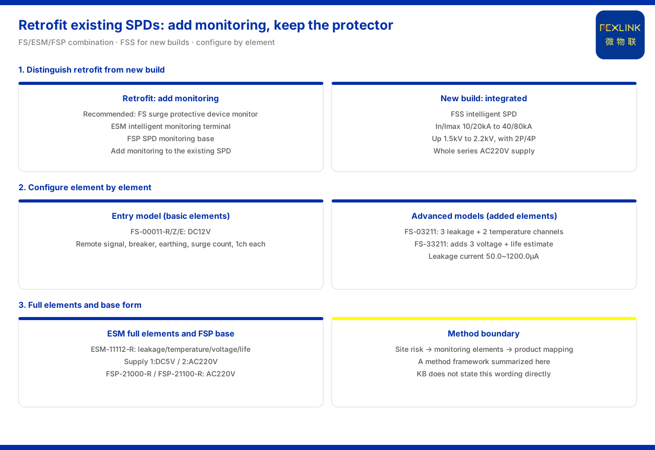
Retrofitting status monitoring onto an existing SPD does not mean replacing the protective device itself; the convention given by the product knowledge base is to overlay a monitoring component onto the surge protective device already in place. The typical application scenarios and selection comparison list "surge-protective-device status monitoring (retrofit of existing SPD)" as a separate row, with a recommended combination of the FS surge protective device monitor, the ESM intelligent lightning-protection monitoring terminal and the FSP SPD lightning-protection base. Retrofit follows a combination of monitoring-type products and base accessories; for a new-build project, the integrated FSS intelligent surge protective device can be chosen to combine protection and monitoring. The difference between retrofit and new-build is expressed in the knowledge base through different recommended combinations rather than two mutually exclusive rules. In selection, first confirm whether the site is retrofit or new-build, then configure item by item according to the elements to be monitored: basic remote signalling, lightning-strike counting, air-switch and grounding status can start from an entry-level model; adding leakage current and temperature moves up to a model with more elements; voltage and life estimation go a step further; and where a base-form monitoring device is needed under an existing arrester, the corresponding base model applies. The knowledge base treats "field risk identification — monitoring elements — product mapping" as a configurable line of thinking; this article follows that order, but it is a framework summarised here and is not stated by the knowledge base in these exact terms.
1. First distinguish retrofit from new-build
The first step in configuration is to distinguish retrofit from new-build. The typical application scenarios and selection comparison list nine classes of scenario in total, of which only "surge-protective-device status monitoring (retrofit of existing SPD)" explicitly corresponds to a retrofit; the other scenarios, such as online grounding-grid monitoring of substations and traction substations, lightning and explosion protection for tank farms and petrochemicals, and data-centre neutral-to-earth voltage monitoring, are given as system combinations. The difference between retrofit and new-build is thus expressed in the knowledge base through different recommended combinations: the retrofit scenario recommends monitoring and base accessories such as FS, ESM and FSP, whose common feature is overlaying monitoring capability on an existing arrester; a new-build project can use the FSS intelligent surge protective device, in which the device itself carries both protection and monitoring. Therefore, if the site already has a surge protective device and only status monitoring is to be added, the retrofit row applies; if the arrester itself is to be newly installed, the integrated option is preferred.
2. The FS surge protective device monitor: stacking by element
The core monitoring product for retrofit is the FS surge protective device monitor (FS-00011-R/Z/E). The product knowledge base records that it is supplied at DC12V and provides one channel each of remote signalling, air-switch status, grounding status and lightning-strike counting. On that basis, the FS-03211 series adds three leakage-current channels and two temperature channels, and the FS-33211 series further adds three voltage channels and one life-estimation channel. The same product line is thus divided into several steps by the number of monitoring elements: the entry step answers "has it operated, has it switched, is grounding normal, has there been a lightning strike"; the middle step adds leakage current and temperature for observing the deterioration trend of the arrester; and the top step adds voltage and life estimation. On parameters, the leakage-current monitoring range is 50.0 to 1200.0 microamperes with a deviation of ±10 microamperes; the lightning-strike counting range is 0 to 9999 strikes with a minimum trigger of 0.1 kiloampere; and the voltage monitoring range is 0 to 400.0 volts with a deviation of ±0.1 volt. In selection, choose the step according to the elements the site cares about, without having to go to the top in one move.
3. The ESM intelligent lightning-protection monitoring terminal: the full-element version
If a retrofit SPD needs more complete full-element monitoring, the ESM intelligent lightning-protection monitoring terminal can be chosen. The model rules given by the product knowledge base encode power supply, display and version into the model: power code 1 means DC5V and 2 means AC220V; display code 1 means digital tube and 2 means OLED; and version code 1 means the basic four-element version and 2 means the flagship multi-element version. By these rules, the model ESM-11112-R contains leakage current, temperature, voltage and life estimation, and can be used to overlay full-element monitoring on an existing arrester. Understanding this encoding turns selection into confirming digit by digit: set the power digit by the site supply, then the display and version to fix the element step, and finally check whether the multi-element version is needed. The relation between ESM and FS can be understood as follows: FS segments its models by element, while ESM splits power, display and element version into combinable digits; both address the overlay scenario of retrofit.
4. The FSP SPD lightning-protection base: monitoring in base form
Another form for retrofit is the SPD lightning-protection base. The product knowledge base records that both the FSP SPD lightning-protection base (FSP-21000-R) and the FSP SPD lightning-protection base (FSP-21100-R) use AC220V supply, a digital-tube display and RS485 communication. The two differ in monitoring elements: FSP-21000-R provides one remote-signalling input, one lightning-strike counting channel and zero temperature channels, whereas FSP-21100-R provides one remote-signalling input, one lightning-strike counting channel and one temperature channel. Their positioning is as a monitoring base used together with a surge protective device, that is, building the monitoring capability into the arrester's mounting base rather than using an external standalone monitor. In selection, if the site wishes to read status in the original arrester position without adding a separate monitoring device, the base form can be brought into the comparison; whether the extra temperature channel is wanted is decided between the two models.
5. The FSS intelligent surge protective device: the integrated new-build choice
For a new-build project, protection and monitoring can be considered together. The product knowledge base records that the whole FSS intelligent surge protective device series is supplied at AC220V, that the nominal discharge current and maximum discharge current cover 10 kiloamperes and 20 kiloamperes to 40 kiloamperes and 80 kiloamperes, that the voltage protection level covers 1.5 kilovolts to 2.2 kilovolts, that the pole count includes 2P and 4P, and that the leakage-current version uses an OLED display. A new-build project can therefore choose an integrated protection-plus-monitoring device that performs both protection and status acquisition itself, without overlaying a separate monitor. In selection, fix the current step, voltage protection level and pole count by system requirement, then check whether the leakage-current display version is needed. It should be noted that the integrated option corresponds to new-build; the retrofit scenario does not presuppose replacing the protective device itself, and the two sit under different recommended combinations.
6. The check order for mapping elements to models
Bringing the product lines together gives a check order for retrofit. First, confirm whether the site is retrofit or new-build: retrofit falls to the monitoring and base combination, and new-build considers the integrated option. Second, define the elements to be monitored: basic remote signalling, air-switch, grounding and lightning-strike counting, or additionally leakage current, temperature, voltage and life estimation. Third, choose the carrying form among the element steps of FS, the version encoding of ESM and the two base models of FSP. Fourth, confirm power, display, elements and communication digit by digit according to the model rules, and verify consistency with site conditions. Fifth, return to the typical scenario table and check whether the chosen combination agrees with the recommended convention in the "surge-protective-device status monitoring (retrofit of existing SPD)" row. By this order, selection for retrofit of an existing SPD moves from scenario to model, with each step traceable.
Scope and limitations
First, this article restates only what the product knowledge base records; the factual boundary is limited to the seven classes of the intelligent lightning-protection product line, the recommended combination of the retrofit-SPD scenario, and the related FS, ESM, FSP and FSS models and parameters.
Second, the difference between retrofit and new-build is cited as the knowledge base expresses it, through different recommended combinations; this article does not infer other retrofit methods or product combinations not listed.
Third, the recommended FS, ESM and FSP combination for the retrofit-SPD scenario is cited as listed, without extending to other scenarios.
Fourth, the FS element steps and parameters, the ESM model rules and the elements of ESM-11112-R, the elements, supply, display and communication of the two FSP models, and the supply, current, voltage protection level, pole count and leakage-current display version of FSS are all cited as the knowledge base lists them.
Fifth, this article only explains the monitoring-selection method and product mapping for retrofit of an existing SPD; it provides no grading configuration, parameter value or setting scheme for a specific project, and related conclusions must be determined with site conditions and the project scheme.


