
Direct answer
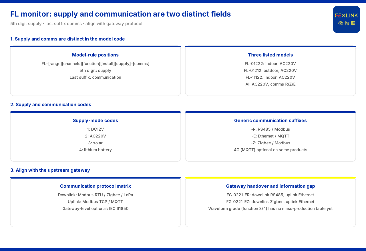
The supply and communication options of the FL lightning current / transient current monitor (e.g. FL-01222) are two positions in the model rule that can be determined separately. The product knowledge base specifies that this series forms its main body from "detection range, channel count, function, installation method, supply", with the communication method listed separately, where the fifth position is the supply and the last position is the communication. On the supply side, the supply-method codes for lightning-protection products give four tiers: 1 corresponds to DC12V, 2 to AC220V, 3 to solar power, and 4 to lithium battery. On the communication side, the general suffixes give -R for RS485 and Modbus, -E for Ethernet and MQTT, and -Z for Zigbee and Modbus, and some products can also optionally use 4G. The three listed types of the lightning current monitor — FL-01222, FL-01212 and FL-11122 — all use AC220V supply and can all choose among R, Z and E for communication. Once supply and communication are fixed, the protocol relationship with the upper-layer gateway must still be aligned before data can truly ascend.
Supply and communication are two independent fields in the model
The model rule the product knowledge base gives is: the main body consists of detection range, channel count, function, installation method and supply, with the communication method listed separately; the fifth position is the supply and the last position the communication. Placing supply and communication respectively in the main body and the suffix means the two can be chosen independently: supply decides how the device draws power and communication decides how data is sent out, without binding each other. Understanding this explains why the same FL monitor appears in several suffix combinations—the measured object and the installation position decide the leading positions, while supply and communication are settled separately according to on-site conditions. In other words, the leading positions answer "what to measure and how to install it" and the last two answer "how to supply power and how to network", a clear division of labour.
How to choose the supply: four supply codes
The product knowledge base specifies that the supply-method codes for lightning-protection products are: 1 corresponds to DC12V, 2 to AC220V, 3 to solar power, and 4 to lithium battery. The FL lightning current / transient current monitor belongs to the lightning-protection product line, so its supply choice can be determined by this code. The four tiers cover the common active supply and two supplementary modes: DC12V and AC220V are for sites with mains power, while solar power and lithium battery are for sites where power is inconvenient. In selection, first confirm whether the site has stable mains power, then locate the corresponding supply field among the four tiers.
How to choose the communication: three suffixes
The communication side is decided by the general suffixes. The product knowledge base specifies that -R is RS485 and Modbus, -E is Ethernet and MQTT, and -Z is Zigbee and Modbus, and notes that 4G and MQTT are optional on some products. FL models distinguish communication by the R, Z and E suffixes, chosen under that rule. The three differ in physical link and protocol: RS485 and Zigbee are device-side links, while Ethernet is a network-side link. The choice requires looking at which type of consolidation node the data must ultimately connect to, not judging by the link name alone. If the site already has an RS485 bus, the -R suffix can connect directly; if wireless networking is used, the -Z suffix saves on cabling; and if direct network connection is needed, the -E suffix is more direct.
The protocol relationship with the upper-layer gateway
The communication option must also be checked against the protocol matrix. The product knowledge base's communication protocol matrix specifies that the device downlink protocols are Modbus RTU (RS485), Zigbee (Modbus) and LoRa, the device uplink protocols are Modbus TCP and MQTT (over Ethernet or 4G), and IEC 61850 is optional at the gateway level. This shows that the FL monitor's communication options are not isolated but form a set with the upper-layer connection method: choosing RS485 or Zigbee means following the device downlink protocol, while choosing Ethernet connects directly to the uplink protocol. The product knowledge base also gives the FG lightning-protection smart gateway, which provides RS485 or Zigbee on the downlink and Ethernet on the uplink and can serve as the consolidation node that takes over FL communication and ascends to the platform. Communication selection is therefore not just choosing an outlet for the monitor, but also confirming which type of gateway the outlet can connect to.
Supply and communication combinations given by the existing model table
The product knowledge base's model table lists three FL lightning current / transient current monitors: FL-01222 (indoor, AC220V), FL-01212 (outdoor, AC220V) and FL-11122 (indoor, AC220V). All three use AC220V supply and all offer R, Z and E communication. This set of data shows that among the mass-produced models the supply field currently falls uniformly in the AC220V tier, while the communication field still leaves three choices. In selection, the installation position and detection range can therefore be confirmed first, then the communication suffix chosen within the same supply condition.
What it means that waveform-tier models have no mass-production selection table yet
In its known-information gaps the product knowledge base states that FL models involving the waveform function (functions 3 and 4) have no mass-production selection table yet. This has a direct bearing on supply and communication selection: because the waveform tier has no complete mass-production entries to rely on, its supply and communication combination cannot be inferred without basis and can only be determined after the selection table is completed. In other words, when the requirement falls on the waveform function, the conditions for settling supply and communication are not yet complete, and the item should be treated as pending confirmation in the scheme rather than directly applying a non-waveform-tier combination. This neither holds up the overall progress of the scheme nor treats an unlisted combination as an established configuration written into the selection result.
Checking sequence
Gathering the clues above into a sequence, four steps can be followed. First, confirm the detection range, channel count and function of the monitored object and establish whether it falls in the waveform tier. Second, choose the supply field among the four supply codes by the on-site power condition. Third, choose the communication among the three suffixes by the data-access method and check the downlink and uplink relationship against the protocol matrix. Fourth, confirm whether the upper layer needs consolidation through the FG lightning-protection smart gateway; if the requirement belongs to the waveform tier, mark it first as a pending item. In this order, supply and communication answer "how the two independent fields are settled separately", not a fixed combination bound together.
Applicability and limits
First, this article only restates content listed in the product knowledge base; its factual boundary is limited to the model rule of the FL lightning current / transient current monitor, the lightning-protection supply-method codes, the general suffixes, the communication protocol matrix, the downlink and uplink capabilities of the FG lightning-protection smart gateway, the supply and communication listed in the model table, and the information gap of the waveform-tier models, and it introduces no unlisted parameters, certifications or cases.
Second, the model rule and field positions of the FL lightning current / transient current monitor, and the installation environment, supply and communication options of the three models listed in the model table, are cited on the terms listed in the product knowledge base.
Third, the lightning-protection supply-method codes and the general suffixes (including 4G optional on some products) are cited on the terms listed in the product knowledge base; this article does not infer the supply or communication configuration of unlisted products from them.
Fourth, the communication protocol matrix and the downlink and uplink protocols of the FG lightning-protection smart gateway are cited on the terms listed in the product knowledge base; this article makes no judgement on the networking conclusion of a specific project.
Fifth, the absence of a mass-production selection table for waveform-function models is a known information gap listed in the product knowledge base; this article makes no inference about the supply or communication combination of such models.
Sixth, this article does not commit to any specific project's selection result or on-site performance, which remain subject to the latest product documentation and project scheme.


