
Direct answer
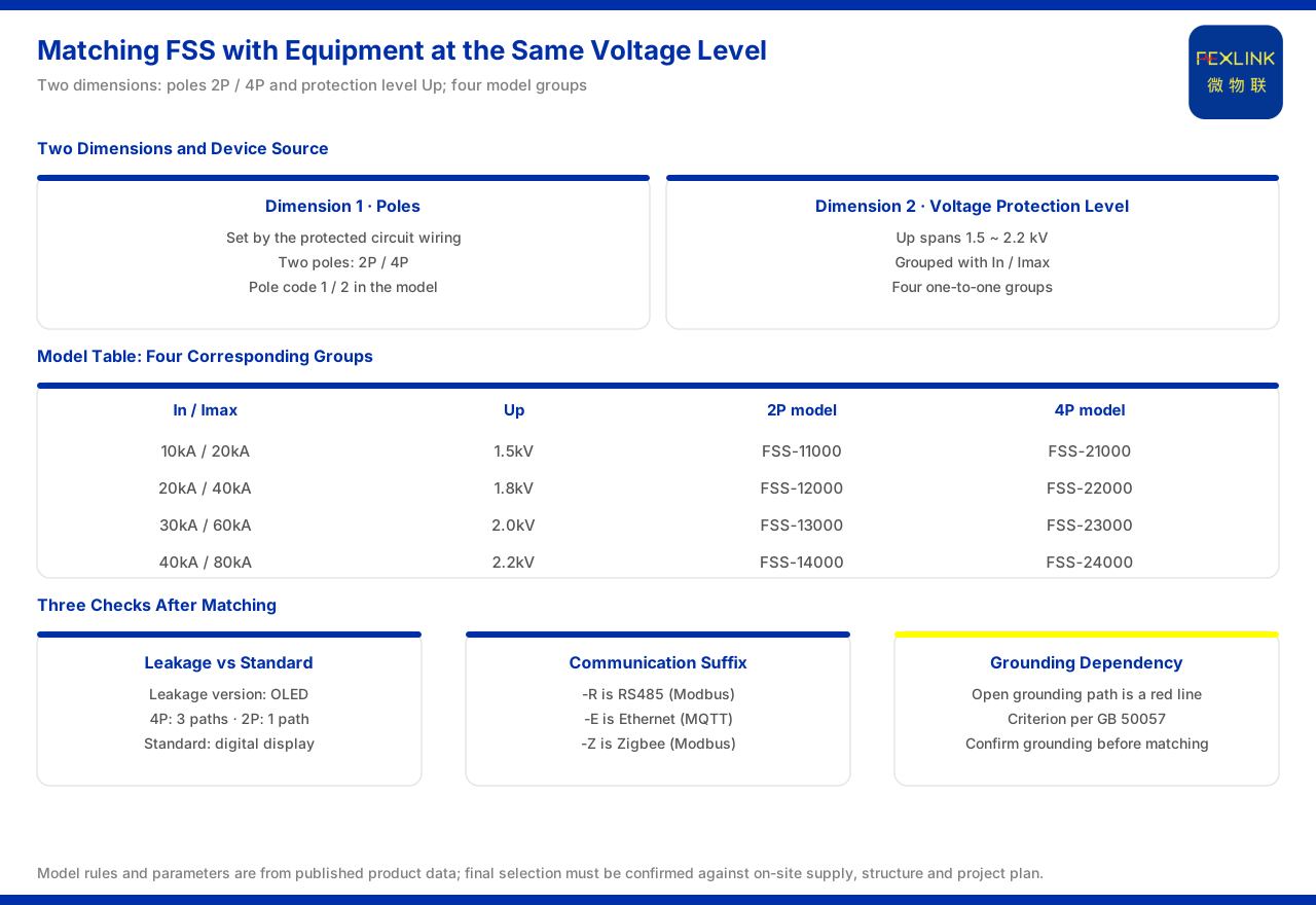
The matching of the FSS intelligent surge protective device (e.g. FSS-11000) to the protected equipment rests on two dimensions: phase count and voltage protection level. The product knowledge base specifies that its model rule is formed by phase count, varistor class, leakage current and two reserved positions in the body segment, with communication listed separately; phase count 1 is 2P and 2 is 4P, and varistor classes 1 to 4 correspond to maximum discharge current Imax of 20kA, 40kA, 60kA and 80kA. The model table gives nominal and maximum discharge current together with the voltage protection level in groups: the 10kA / 20kA group corresponds to 1.5kV, the 20kA / 40kA group to 1.8kV, the 30kA / 60kA group to 2.0kV, and the 40kA / 80kA group to 2.2kV. Matching therefore does not begin with "which model has higher parameters" but by confirming whether the protected circuit is 2P or 4P and what voltage protection level the equipment can withstand, then choosing the corresponding tier from the model table. The product knowledge base gives no rule of "deducing the voltage protection level from the protected equipment's withstand voltage", and the matching principle must be generalised from the two dimensions of phase count and voltage protection level.
1. First clarify which product line the FSS belongs to
Before matching, confirm the device's ownership, because different product lines lead to different selection landing points. In the product-line overview of the product knowledge base, the A intelligent lightning-protection line contains the intelligent surge protective device, an in-house intelligent lightning-protection product; the E surge protective devices line is the outsource-supported YSE series, and the two belong to two lines. The selection of the intelligent surge protective device therefore lands on the model rule and parameter table given by the product knowledge base, and is not mixed with outsource-supported SPDs. This is stated first because the matching principle applies only to models within the in-house line: it concerns phase count, varistor class and leakage current, not the discharge tiers of outsource-supported SPDs.
2. First matching dimension: 2P or 4P phase count
Phase count is the first dimension of matching, because it is decided by the wiring system of the protected circuit. The product knowledge base specifies that in the model rule the phase position 1 is 2P and 2 is 4P; the model table is also divided into two groups by phase count, with 2P and 4P types appearing in pairs under the same varistor class. Taking the 10kA / 20kA tier as an example, the corresponding models are FSS-11000 and FSS-21000, the former 2P and the latter 4P; the other tiers are likewise given in pairs by this pattern. This shows that the phase count is not a feature optional afterwards but a field that must first be aligned with the protected circuit: first determine whether the circuit is two-wire or four-wire, then choose the varistor class and leakage-current configuration under that phase count.
3. Second matching dimension: voltage protection level 1.5 to 2.2kV
The second dimension is the voltage protection level. The model table of the product knowledge base binds the nominal and maximum discharge current to the voltage protection level, forming four correspondences: 10kA / 20kA to 1.5kV, 20kA / 40kA to 1.8kV, 30kA / 60kA to 2.0kV, and 40kA / 80kA to 2.2kV. This means that a higher surge-protection capability corresponds to a higher voltage protection level, one to one across the four groups. In matching, first confirm the degree to which the protected equipment tolerates a limiting voltage, and choose the corresponding voltage protection level tier accordingly, rather than picking a discharge-current figure alone. Note that the product knowledge base gives no selection table of "deducing the voltage protection level from the protected equipment's withstand voltage"; this article explains the matching dimensions only by the listed group correspondences and does not replace the on-site grading scheme in drawing a value conclusion.
4. The four corresponding groups of the model table
Reading the phase count and varistor class together, the correspondences of the model table can be set out as follows:
| Nominal / maximum discharge current | Voltage protection level | 2P model | 4P model | |:--|:--|:--|:--| | 10kA / 20kA | 1.5kV | FSS-11000 | FSS-21000 | | 20kA / 40kA | 1.8kV | FSS-12000 | FSS-22000 | | 30kA / 60kA | 2.0kV | FSS-13000 | FSS-23000 | | 40kA / 80kA | 2.2kV | FSS-14000 | FSS-24000 |
As the table shows, each group is jointly defined by phase count and discharge capability: first fix the phase count, then fix the discharge capability and voltage protection level, and neither dimension can be omitted. The whole series is supplied at AC220V with 2P or 4P poles.
5. Difference between the leakage-current version and the standard version
After fixing the phase count and varistor class, confirm whether leakage-current monitoring is needed. The product knowledge base records that the leakage-current version targets the model groups whose leakage-current position is 1, such as FSS-11100 / 21100, FSS-12100 / 22100, FSS-13100 / 23100 and FSS-14100 / 24100; they display on OLED and include leakage-current monitoring, in which the 4P type has 3 leakage-current channels and the 2P type has 1. The standard version, by contrast, displays on digital tubes. This difference shows that the leakage-current position does not change the phase count or discharge capability, only whether leakage-current monitoring is included in the body; whether leakage current is needed should be decided by whether leakage state is to be observed on the protected circuit, not treated as a bonus of the varistor class.
6. Communication suffix and grounding dependency
Matching also involves two supporting matters: how data is sent out, and whether grounding is reliable. The general suffix rule of the product knowledge base specifies that -R is RS485 (Modbus), -E is Ethernet (MQTT) and -Z is Zigbee (Modbus), with 4G (MQTT) optional for some products; the intelligent surge protective device supports RS485 across the whole series and selects Zigbee and Ethernet by suffix, so the communication method must be matched together with on-site networking during selection. On grounding, the safety red-line guard specifies that "abnormal open circuit of grounding resistance" is a non-bypassable red line, based on GB 50057; as the SPD body, the intelligent surge protective device depends on the grounding path for normal operation, and a grounding abnormality is a national-standard red-line criterion. Matching therefore also requires confirming that the grounding condition holds.
7. Reducing the matching principle to a check list
Putting the above together, the matching principle reduces to a check list. First, confirm the device source: this topic faces only the intelligent surge protective device within the in-house intelligent lightning-protection line, not mixed with outsource-supported SPDs. Second, confirm the phase count: whether the protected circuit is 2P or 4P, and choose the corresponding phase group of the model table. Third, confirm the voltage protection level and discharge capability: choose by the four group correspondences of 1.5kV to 2.2kV, not by the discharge current alone. Fourth, confirm leakage current: whether leakage-current monitoring is needed decides the leakage-current version or the standard version. Fifth, confirm communication and grounding: choose the communication method by suffix and confirm that the grounding condition holds. By this order, matching answers "which tier of model the circuit and equipment conditions correspond to", not "which tier of parameters is higher".
Scope and limitations
First, this article restates only what the product knowledge base lists, with the factual boundary limited to the product-line ownership, model rule, model table, communication suffixes and leakage-current configuration of the intelligent surge protective device, and the grounding-related criterion in the safety red-line guard.
Second, the phase position 1 as 2P and 2 as 4P, varistor classes 1 to 4 corresponding to maximum discharge currents of 20kA, 40kA, 60kA and 80kA, and the group correspondences of nominal / maximum discharge current with voltage protection levels of 1.5kV to 2.2kV, are all cited from the product knowledge base.
Third, the AC220V supply of the whole series, the 2P / 4P poles, the display and leakage-current channel count of the leakage-current version (3 channels for 4P, 1 for 2P) and the digital-tube display of the standard version are all cited from the product knowledge base.
Fourth, the communication suffix rule and the "abnormal open circuit of grounding resistance" criterion in the safety red-line guard and its standard basis are all cited from the product knowledge base.
Fifth, the product knowledge base gives no judgment rule or selection table for matching the intelligent surge protective device to the protected equipment's voltage level; the matching principle is generalised from the two dimensions of phase count and voltage protection level.
Sixth, this article only explains the matching principle and provides no specific project graded configuration, voltage protection level value or setting scheme; the relevant conclusions must be confirmed with the on-site grading scheme and the project solution.


