
Direct answer
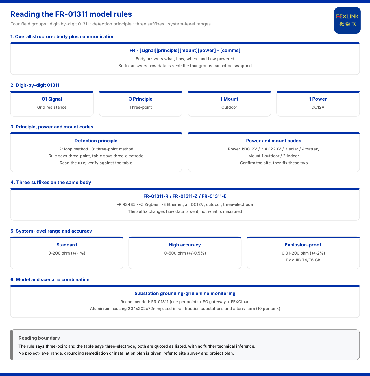
The model rule of the FR grounding resistance monitor (e.g. FR-01311-R) can be read as "a body segment of four field groups plus a communication suffix": the body segment is formed by signal acquisition, detection principle, installation method and power supply, with the communication method listed separately. Taking FR-01311-R as an example, the five digits of the body segment are, in order, signal acquisition, detection principle, installation method and power supply, and the final -R indicates RS485 communication. By the field definitions of the product knowledge base, signal acquisition 01 is the grounding-grid resistance, detection principle 3 is the three-point method, installation method 1 is outdoor, and power supply 1 is DC12V; the model table records this type's measurement method as the three-electrode method. The key to reading this model rule is therefore not to memorise one specific model, but to master the reading "each position corresponds to one site condition": split the positions apart and the model reduces to a set of checkable selection conditions.
1. Overall structure: a body segment of four field groups plus communication
The product knowledge base specifies that the model rule of the FR grounding resistance monitor is: the body segment is formed by four field groups — signal acquisition, detection principle, installation method and power supply — with the communication method listed in the final segment. This structure is consistent with the general writing of lightning-protection products: the body segment answers "what is measured, how, where it is installed, and how it is powered", while the final segment answers "how the data is sent out". Splitting the rule into a "body segment" and a "communication segment" is the first step in reading any FR model. The body segment is itself divided into four groups that cannot substitute for one another; the values of the communication segment come from the general suffix rule rather than being unique to the FR. With this framework, the digits no longer look like meaningless codes.
2. Decoding 01311 position by position
Taking FR-01311 as an example, the five digits of the body segment map, position by position, onto the rule groups. The first two digits together form the "signal acquisition" group with the value 01, corresponding to the grounding-grid resistance, that is, the physical quantity the instrument acquires is the resistance of the grounding grid. The third digit is the "detection principle" group with the value 3, corresponding to the three-point method. The fourth digit is the "installation method" group with the value 1, corresponding to outdoor installation. The fifth digit is the "power supply" group with the value 1; by the supply-mode codes of lightning-protection products, 1 means DC12V. Read together, FR-01311 means a grounding resistance monitor that "acquires the grounding-grid resistance, measures by the three-point method, is installed outdoors and is supplied at DC12V". Each position is thus the projection of a site condition onto the product code, not decoration.
3. The detection-principle position: why it is the key tier
Among the four field groups, the detection-principle position has the most direct effect on selection. The product knowledge base divides it into two tiers: 2 for the loop method and 3 for the three-point method. The two measurement principles correspond to different site conditions and measurement methods, so this position decides how the instrument obtains the grounding-grid resistance. Note that the model rule writes the three-point method, while the model table of FR-01311 records the measurement method as the three-electrode method; the two are the product knowledge base's expressions of the same measurement method. When reading the model, the field definition should be used to understand the position value, and the model table to check a specific model's measurement method, power supply and installation environment; the two must not be confused.
4. Power-supply and installation positions
The power-supply and installation positions are likewise site conditions that can be checked position by position. The supply position uses the supply-mode codes of lightning-protection products: 1 is DC12V, 2 is AC220V, 3 is solar, 4 is lithium battery. The installation position uses 1 for outdoor and 2 for indoor. FR-01311 has supply position 1 and installation position 1, so this type is DC12V-supplied and outdoor-installed. The meaning of these two groups is that they write "what power the site can provide and where the device is installed" into the model, so that selection only needs to confirm the site conditions to fix these two positions, rather than choosing a model and then working backwards.
5. Three communication suffixes of the same model
Models with the same body segment can be derived into different versions by communication suffix. The model table of the product knowledge base lists three FR grounding resistance monitor types — FR-01311-R, FR-01311-Z and FR-01311-E: all are DC12V, outdoor-installed and three-electrode measured, differing only in communication, respectively RS485 (-R), Zigbee (-Z) and Ethernet (-E). This set of comparisons shows that the communication suffix does not change the measurement capability, only how the data is sent out. In selection, the measurement scheme can first be fixed by the four body field groups, and the suffix then chosen according to on-site networking conditions. Deciding the body segment and the suffix separately is exactly what makes this model rule practical.
6. System-level range and accuracy
Beyond the model rule, range and accuracy are given by system-level reference parameters. The grounding resistance monitoring system reference parameters of the product knowledge base group the monitoring unit's range and accuracy: the standard type is 0 to 200Ω (±1%), the high-precision type is 0 to 500Ω (±0.5%), and the explosion-proof type is 0.01 to 200Ω (±2%) with an explosion-proof rating of Ex d IIB T4/T6 Gb. These three tiers show that grounding resistance monitoring does not have only one range but is tiered by measurement occasion; the explosion-proof type faces areas requiring an explosion-proof rating. Range and accuracy do not appear as model positions but are given at system level, so after checking the model one must return to the system parameters to confirm whether the range tier covers the site's magnitude.
7. Model-to-scenario correspondence
In its typical application scenarios and selection comparison, the product knowledge base gives the recommended product combination for the online monitoring of substation and traction-substation grounding grids as: one FR-01311 per grounding point, plus the FG lightning-protection smart gateway (e.g. FG-0221-ER), plus the FEXCloud IoT cloud platform. This combination links the three layers of model, aggregation and platform, showing that the landing point of reading a model rule is not only to pick one instrument but also to clarify its position on the data link. The product knowledge base also notes that the FR and FRP series grounding resistance monitors have been applied to the online monitoring of railway traction-substation grounding grids and to the Jinzhou Port oil tank area (10 sets per tank); these records may serve as a reference for the series' direction of use but constitute no commitment about the results of other projects. Only by aligning the model rule, the system parameters and the scenario combination is an FR model fully understood.
Scope and limitations
First, this article restates only what the product knowledge base lists, with the factual boundary limited to the model rule of the FR grounding resistance monitor, the FR-01311 model table, the housing dimensions, the system-level range and accuracy, and the supply-mode codes and typical application scenario combinations of lightning-protection products, introducing no unlisted parameters, certifications or cases.
Second, the field definitions of the model rule and the measurement method, power supply, installation environment and communication of the FR-01311-R / Z / E types are cited from the product knowledge base; where the model rule writes the three-point method and the model table records the three-electrode method, this article transcribes both without further technical inference.
Third, the FR housing dimensions of aluminium 204×202×72mm, and the system-level standard type 0 to 200Ω (±1%), high-precision type 0 to 500Ω (±0.5%), explosion-proof type 0.01 to 200Ω (±2%) and explosion-proof rating Ex d IIB T4/T6 Gb, are cited from the product knowledge base.
Fourth, the application records such as railway traction-substation grounding-grid online monitoring and the Jinzhou Port oil tank area (10 sets per tank) are listed by the product knowledge base; this article only transcribes them and does not represent a commitment about the results of other projects.
Fifth, this article only explains how to read the FR model rule position by position and provides no specific project range selection, grounding rectification or installation scheme; the relevant conclusions must be confirmed with site survey and the project solution.
Sixth, this article constitutes no commitment about the selection result or field behaviour of a specific project; actual conditions are subject to the latest product material and project solution.


