
Direct answer
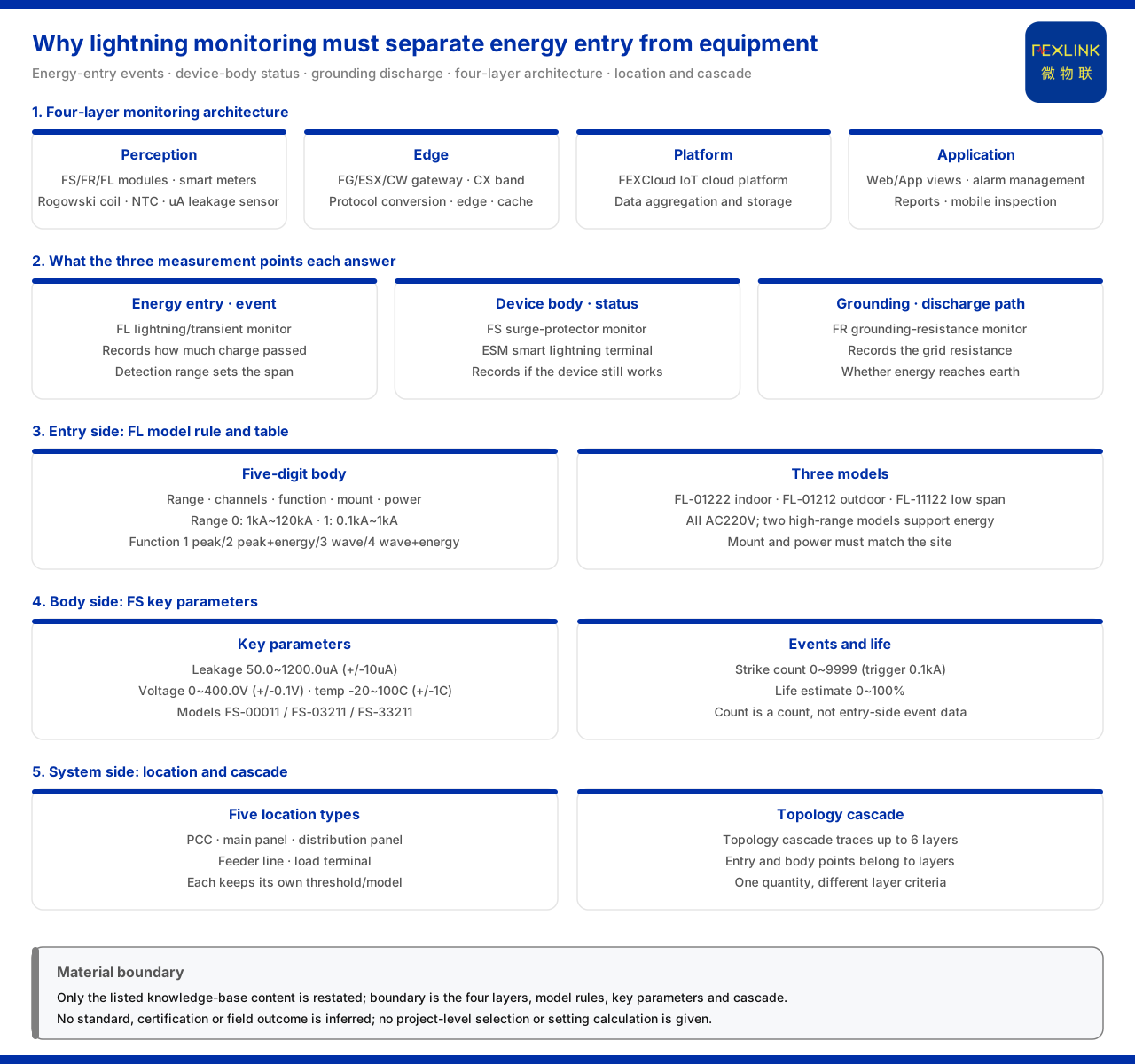
The points of a lightning-strike monitoring layout must distinguish the energy entry from the equipment body, because these two layers answer different questions: the entry layer answers "where the energy enters and how large it is", while the body layer answers "whether the equipment that receives the energy is still serviceable". In the general four-layer architecture of the monitoring system, the product knowledge base puts two kinds of unit among the perception layer's acquisition objects at the same time: the device-state acquisition unit represented by the FS surge protective device monitor (e.g. FS-00011-R) and the ESM intelligent lightning-protection monitoring terminal (e.g. ESM-11312-R), and the lightning-current event acquisition unit represented by the FL lightning current / transient current monitor (e.g. FL-01222-R); on the grounding-grid side, the FR grounding resistance monitor (e.g. FR-01311-R) carries the role. With points only on the body, one sees degradation but not where the energy entered; with points only at the entry, one has event records but no view of whether the device and grounding path can still take the next impact. A layered layout lets event information and state information each take their proper place.
1. What each of the two monitoring layers looks at
The product knowledge base summarises the monitoring system as a four-layer architecture of perception, edge, platform and application. The perception layer acquires data from monitoring modules, smart meters and sensors, and on the sensor side includes Rogowski coils, NTCs and microampere-level leakage-current sensors. Among these, the FL lightning current / transient current monitor records "how much electricity flowed through", an event quantity of energy entry and discharge; the FS surge protective device monitor and the ESM intelligent lightning-protection monitoring terminal record "what state the device is in at this moment", a body quantity; and the FR grounding resistance monitor records "whether the energy can finally be discharged into the earth", a grounding-path quantity. The three fall respectively at energy entry, device reception and energy discharge, and this is where the layered layout is needed.
2. On the energy-entry side: record events, not states
The landing point on the entry side is lightning current monitoring. The product knowledge base specifies that the model rule of the FL lightning current / transient current monitor is: the body segment is formed by detection range, channel count, function, installation method and power supply, with communication listed separately. The detection range has two tiers, 0 covering 1kA to 120kA and 1 covering 0.1kA to 1kA; the function has four tiers, 1 for peak, 2 for peak plus energy, 3 for waveform and 4 for waveform plus energy. This rule shows that the entry side must acquire the magnitude and shape of the event itself, not the health of a device. In the model table, the FL-01222 is an indoor type and the FL-01212 an outdoor type, both supplied at AC220V, with a peak range of 1kA to 120kA and support for energy; the FL-11122 has a peak range of 0.1kA to 1kA.
3. On the equipment-body side: record state, not events
The landing point on the body side is surge protective device state monitoring. The product knowledge base gives the key parameters of the FS surge protective device monitor: leakage current 50.0 to 1200.0μA (±10μA), voltage 0 to 400.0V (±0.1V), temperature -20 to 100℃ (±1℃), lightning count 0 to 9999 times (minimum trigger 0.1kA) and lifespan estimation 0 to 100%. Its model rule is formed by voltage channels, leakage-current channels, temperature channels, digital inputs and the grounding / lightning-strike element positions; the model table lists the SPD monitor's FS-00011, FS-03211 and FS-33211, all providing remote signalling, air-switch state, grounding state and lightning count at DC12V, with the latter two adding leakage current and temperature and the highest type also including voltage and lifespan estimation. Note that although the lightning count relates to lightning, it records a "number of times", not the strength of each event, so it is a body-state quantity and cannot replace entry-side event acquisition. For fuller coverage, the ESM intelligent lightning-protection monitoring terminal covers digital quantities, grounding state, lightning count, leakage current, temperature, voltage, humidity and lifespan estimation.
4. The grounding grid is the channel for energy discharge
Even if the energy is recorded at the entry and received by the device beforehand, it must ultimately be discharged into the earth through the grounding grid. The product knowledge base specifies that the model rule of the FR grounding resistance monitor is: the body segment is formed by signal acquisition, detection principle, installation method and power supply, with communication listed separately; detection principle 2 is the loop method and 3 the three-point method, installation method 1 is outdoor and 2 indoor, and signal acquisition 01 is the grounding-grid resistance. In the model table, the grounding monitor's FR-01311-R, FR-01311-Z and FR-01311-E are all DC12V, outdoor installation and three-electrode measurement, with communication respectively RS485, Zigbee and Ethernet; the housing is aluminium, 204×202×72mm. The observable quantity on the grounding side is the grounding-grid resistance, answering whether the discharge channel is unobstructed.
5. How the model rules reflect the layering
Placing the above rules side by side, the boundary of the layering is clear: entry-side products begin with "detection range" because what they distinguish is the energy magnitude; body-side products begin with "voltage channels / leakage-current channels" because what they distinguish is element coverage; grounding-side products begin with "signal acquisition" because what they distinguish is the measured physical quantity. The difference of fields is the imprint the layered layout leaves at the product level. This is why the model rules cannot be applied across series: the magnitude field on the entry side cannot describe the degradation state of the body, and the element field on the body side cannot describe the energy magnitude.
6. On the system side: position and cascading
A layered layout is meaningful only when it lands on the system side. The product knowledge base records that the location awareness of the Wanxiang engine maintains independent thresholds and risk models for five types of electrical topology position, namely the point of common coupling, the main distribution panel, the distribution panel, the feeder line and the load terminal; the topology-cascade impact capability traces up to 6 levels. Putting the entry and body acquisition points into this framework makes clear why the same quantity needs different criteria at different positions: entry-side event data describes "how strong the impact is", body-side state data describes "whether the receiver is still serviceable", and position and cascade relations determine to which level the impact propagates. A layered layout is therefore not a stacking of points, but a placement of each point on the layer it can truly observe.
7. An operable checking order
These threads reduce to four steps. First, ask whether this monitoring answers an event question or a state question: to reconstruct the lightning process, place the point on entry-side lightning current monitoring. Second, to judge continued serviceability, place the point on body-side surge protective device state monitoring, choosing between the surge protective device monitor and the intelligent lightning-protection monitoring terminal by element coverage. Third, confirm whether the discharge channel is observed: to know the grounding-grid resistance, choose the grounding resistance monitor. Fourth, return to the system side and check, by position type and cascade relations, which layer each point belongs to. By this order, the layered layout answers "what each layer is missing", not "which product is better".
Scope and limitations
First, this article restates only what the product knowledge base lists, with the factual boundary limited to the general four-layer architecture of the monitoring system, the core sensor technology, the model rules and key parameters of the lightning-protection products, and the records on topology position and cascade impact.
Second, the monitoring elements, model rules and parameters of the surge protective device monitor, and the model rules and element coverage of the intelligent lightning-protection monitoring terminal, are cited by the specifications listed in the product knowledge base; this article infers no unlisted configuration and applies no parameters across the two classes.
Third, the detection-range and function tiers of the lightning current / transient current monitor, the installation environment, power supply and energy support in its model table, and the model rules, model table and housing dimensions of the grounding resistance monitor, are cited from the product knowledge base.
Fourth, the five types of electrical topology position and the topology-cascade impact tracing up to 6 levels are cited from the product knowledge base; this article draws no conclusion about the criterion values or point counts of a specific project.
Fifth, this article only explains why the entry layer and the body layer need a layered layout and provides no specific project selection, setting or configuration calculation; the relevant conclusions must be confirmed with site conditions and the project solution.
Sixth, this article constitutes no commitment about the selection result or field behaviour of a specific project; actual conditions are subject to the latest product material and project solution.


