
Direct answer
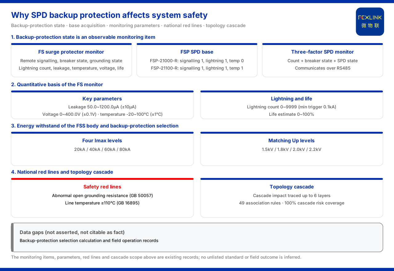
Under the specification of the product knowledge base, the open/closed state of SPD backup protection is not an invisible operation-and-maintenance blind spot: the monitoring elements of the surge protective device monitor (e.g. FS-00011-R) expressly include "air-switch state" and "SPD state", its model rule encodes switching-quantity, grounding and lightning-strike elements into positions, and the three-element SPD monitor combines "count, air-switch state and SPD state" and provides the data over RS485. This shows that whether the backup protection (air switch or circuit breaker) has operated is an online visible monitoring item. It affects system safety because the backup protection is the precondition for the effective operation of the SPD: once the backup protection is abnormal, the SPD itself, even if intact, may be unable to operate as required during a lightning strike. The material also gives tools and a bottom line for assessing the scope of this impact, through the topology-cascade impact capability and the national-standard red lines.
1. Where the backup protection sits
In its section on the surge protective device monitor, the product knowledge base lists the objects this device monitors on the power path: remote signalling, air-switch state, grounding state, lightning count, leakage current, temperature, voltage and life estimation. Among them, the "air-switch state" channel corresponds precisely to the observable point of the action of the SPD backup protection (air switch or circuit breaker). Listing "air-switch state" and "SPD state" as monitoring items at the same time shows in itself that the material treats the backup protection and the SPD body as two objects that need to be observed separately: whether the former has opened and whether the latter is still intact do not have the same answer.
2. Why air-switch state is an observable point
In its selection comparison, the product knowledge base lists the three-element SPD monitor: its combination is count, air-switch state and SPD state, with RS485 communication; by contrast, the ordinary lightning counter counts only and has no communication, and their reference prices are 145 and 90 respectively. The three-element monitor brings the backup protection's "air-switch state" into SPD online monitoring, which means that "whether the backup protection has cut off" no longer depends on manually inspecting the air-switch handle on site, but can be reported continuously by the device. From this contrast it can be seen that whether the air-switch state is monitored is one of the things that distinguishes the three-element monitor from the ordinary counter.
3. How the monitor collects the backup-protection state
The device carrying this acquisition is the surge protective device monitor. The product knowledge base gives its model rule: it is formed from positions for voltage channels, leakage-current channels, temperature channels, switching quantities, grounding and lightning strike, with the communication method listed separately. The material also gives key parameters: leakage current 50.0 to 1200.0μA (±10μA), voltage 0 to 400.0V (±0.1V), temperature -20 to 100℃ (±1℃), lightning count 0 to 9999 times (minimum trigger 0.1kA), and life estimation 0 to 100%. These parameters are used to assess the ageing of the SPD and the state after the backup protection operates, and are the quantified basis of system safety monitoring. Observing the air-switch state and these parameters on the same device allows one to see the associated signals of voltage, temperature and life at the same time as judging whether the backup protection has operated.
4. The base and the three-element monitor's supplement
Beyond the monitor, the product knowledge base also lists two models of the SPD lightning-protection base: FSP-21000-R is AC220V, digital-tube display, remote-signalling input 1, lightning count 1, temperature 0 and RS485; FSP-21100-R is AC220V, digital-tube display, remote-signalling input 1, lightning count 1, temperature 1 and RS485. The base's remote-signalling and temperature acquisition of the SPD state is the underlying means of judging whether the backup protection has operated and whether the SPD is abnormal. Together with the three-element monitor and the monitor, it forms the product combination for observing the backup-protection state: the base provides remote signalling and temperature, the monitor provides the complete set of power-path elements, and the three-element monitor packs the key states in the form of "count plus air-switch state plus SPD state" for uplink.
5. The SPD body's energy parameters and backup-protection matching
For the backup protection to serve the SPD, the energy-withstand parameters of the SPD body determine the matching relation. The product knowledge base gives the model rule of the intelligent surge protective device (e.g. FSS-11000): it is formed from phase count, varistor level, leakage current and reserved positions, with communication listed separately. Its nominal discharge current and maximum discharge current provide four steps of 10kA/20kA, 20kA/40kA, 30kA/60kA and 40kA/80kA, corresponding to voltage protection levels 1.5/1.8/2.0/2.2kV, with a pole count of 2P or 4P and digital-tube display; the leakage-current versions (e.g. FSS-11100, FSS-21100) have an OLED display and 1 or 3 leakage-current channels. The material states that the energy withstand of the SPD body and the selection of the backup protection must be matched according to these parameters. That is, the backup protection is not a universal accessory but corresponds to the energy class of the SPD, and whether the two match bears directly on whether the SPD can be effectively engaged during a lightning strike.
6. The impact propagates along the topology cascade
The impact of an abnormal backup protection is not confined to a single SPD. The product knowledge base records that the topology-cascade impact engine of the Wanxiang engine (large model) can trace at most 6 levels of topology impact; the same section gives specifications such as alarm compression 80%, root-cause accuracy above 85%, scenario positioning precision at L17 to L18, and cascading risk coverage 100%, and lists 49 cross-dimensional association rules, for example rising leakage superimposed on temperature anomaly pointing to comprehensive insulation degradation. Placing SPD backup-protection failure in this view explains why it is a system-safety issue: once the backup protection is abnormal, the impact conducts along the electrical topology to adjacent levels rather than stopping at the monitored point. The material provides cascade tracing and association rules precisely to bring this conduction relation into the scope of assessment.
7. National-standard red lines
Above the analysis above there is also a bottom line that cannot be bypassed. In the red-line guard of the product knowledge base, one rule states that an abnormal open circuit of grounding resistance is a non-bypassable red line, with GB 50057 as the basis, and another states that a line temperature reaching 110℃ is a non-bypassable red line, with GB 16895 as the basis. SPD backup-protection failure may cause an abnormality in the grounding path or the SPD path, and these two national-standard red lines constitute the bottom-line criteria of system safety: however the cascade analysis unfolds, a situation touching a red line must be responded to unconditionally.
Scope and limitations
First, the citations in this article are limited to the product material and the corresponding fact pack, and introduce no parameter, certification or case not listed.
Second, the monitoring elements, model rule and key parameters (leakage current, voltage, temperature, lightning count, life estimation) of the surge protective device monitor are limited to the material entries; this article infers no unlisted configuration from them.
Third, the combination, communication and reference prices of the three-element SPD monitor and the ordinary lightning counter, and the model rule, current steps, voltage protection levels, pole counts and display specification of the intelligent surge protective device, are cited as given; the reference prices are for cost reference only, and this article treats them as no quotation commitment.
Fourth, the model, remote-signalling input, lightning count, temperature and communication specification of the SPD lightning-protection base are limited to the material entries.
Fifth, the topology-cascade impact tracing at most 6 levels, and alarm compression 80%, root-cause accuracy above 85%, scenario positioning precision, cascading risk coverage 100% and the 49 association rules, are cited as given, and this article does not treat them as a commitment for any site.
Sixth, an abnormal open circuit of grounding resistance with GB 50057 as the basis, and a line temperature reaching 110℃ with GB 16895 as the basis, are cited as given; this article lists no other graded threshold.
Seventh, this article explains only the direction of the impact of the backup-protection state on system safety, and provides no selection, setting or configuration calculation for a specific project.


