Direct answer
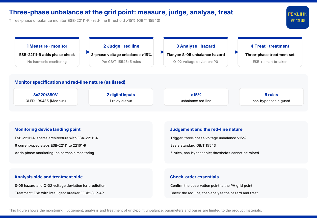
The three-phase unbalance of a PV grid-connection point lands on two stages: device-side monitoring and analysis-side judgement. The product knowledge base records that the three-phase unbalance monitor (e.g. ESB-22111-R) shares the same architecture as the all-parameter smart meter (e.g. ESA-22111-R), adds phase monitoring on that basis, and does not include harmonic monitoring; its specification is 3×220/380V, OLED display, RS485 (Modbus) communication, digital input 2 channels and relay output 1 channel. On the judgement side, the SAR red-line guard of the product knowledge base lists three-phase voltage unbalance (GB/T 15543, >15%) as a red-line trigger condition; the SAR red-line guard has 5 rules in total, which cannot be bypassed, and no one can raise the thresholds. On the analysis side, the S safety-analysis section of the Tianyan engine (large model) contains S-05 three-phase unbalance hazard, one of the P0 first-release models, and is listed together with Q-02 voltage deviation, and can be used for predictive analysis of grid-connection-point unbalance hazards. On the treatment side, the distribution-automation three-phase treatment scenario recommends the three-phase unbalance monitor (ESB) with the intelligent circuit breaker (leakage-protection model) (e.g. FECB2SLP-4P). This article restates only the existing specifications above and infers no measured value of any specific grid-connection point.
1. Why the grid-connection point looks at three-phase unbalance separately
A PV grid-connection point is the interface between the new-energy access and the grid, and the symmetry of the three-phase output is directly related to the grid-connection power quality. Three-phase unbalance is often mentioned together with voltage deviation and harmonics, but their trigger conditions and basis standards are not the same. The product knowledge base lists three-phase voltage unbalance as a separate red-line rule, showing that it has an independent threshold and cannot be judged together with other power-quality indices. Taking the grid-connection point as the observation position is because this is the handover point between the PV side and the grid side: only by monitoring at the grid-connection point can the unbalance state under the joint action of both sides be reflected. If the monitoring point is moved forward or backward, what is seen may be the state at the inverter outlet or on the load side, which cannot represent the true situation at the grid-connection point. The three-phase unbalance at the grid-connection point is therefore a compliance observation point with a definite position and an independent specification, which is not the same as discussing in general terms whether "the system is unbalanced".
2. Monitoring device landing point: the three-phase unbalance monitor
The product knowledge base records that the three-phase unbalance monitor (e.g. ESB-22111-R) shares the same architecture as the all-parameter smart meter, with 6 current-specification steps as ESB-22111 to 22161-R, adds phase-monitoring capability on that basis, and does not include harmonic monitoring. Its specification is 3×220/380V, OLED display, RS485 (Modbus) communication, digital input 2 channels and relay output 1 channel. This group of information defines its position in the solution: it bears the phase-related monitoring of three-phase voltage and current to support the unbalance judgement; since it does not include harmonic monitoring, if the solution also concerns harmonics, a power-quality monitoring type of device must be added separately. During selection one should first confirm whether the monitoring target is "unbalance" or "unbalance plus harmonics", then decide the device combination.
3. Decision red line: three-phase voltage unbalance (GB/T 15543, >15%)
The SAR red-line guard of the product knowledge base lists three-phase voltage unbalance (GB/T 15543, >15%) as a red-line trigger condition. This is a quantified decision specification: a red line is triggered when the three-phase voltage unbalance exceeds 15%. It turns "is the unbalance serious" into a definite threshold judgement and avoids the fuzzy space of empirical description. The judgement at the grid-connection point should take this as its basis rather than replacing it with another scenario or a customary threshold. It should be noted that 15% is the trigger condition listed by the knowledge base, and this article does not interpret it as a relaxation of the permissible range for any site.
4. The nature of the red line: 5 non-bypassable rules
The product knowledge base records that the SAR red-line guard has 5 rules in total, which cannot be bypassed, and no one can raise the thresholds. This nature has direct meaning for a grid-connection-point solution: this red line is not a negotiable alarm reference but a constraint that cannot be relaxed in the process. It means that the 15% threshold should be built in as a rigid condition at the solution-design stage rather than discussed for adjustment only during operation. At the same time, "5 rules" shows that three-phase unbalance is only one of the whole red-line guard; while attending to unbalance, a grid-connection-point solution should also be clear that it exists in parallel with the other red-line rules, each governing its own threshold and not overriding one another.
5. Analysis side: S-05 and Q-02
The product knowledge base records that the S safety-analysis section of the Tianyan engine (large model) contains S-05 three-phase unbalance hazard, one of the P0 first-release models; the P0 first-release models also include Q-02 voltage deviation, applicable to predictive analysis of grid-connection-point unbalance hazards. This shows that grid-connection-point unbalance has not only the real-time judgement of "triggered on exceeding the limit" but also an analysis path facing hazards: S-05 points to the three-phase unbalance hazard itself, and Q-02 points to voltage deviation; the two work together for predictive analysis. Monitoring provides the data, the red line draws the bottom line, and the analysis models use the data for hazard judgement; the three form a complete chain.
6. Treatment and selection landing point
At the treatment level, the product knowledge base writes the recommended combination for the "distribution-automation three-phase treatment" scenario as the three-phase unbalance monitor (ESB) with the intelligent circuit breaker (leakage-protection model) (e.g. FECB2SLP-4P). That is, the monitoring device is responsible for finding the unbalance and the breaker undertakes the corresponding breaking and protection, and the two are used as a set. This is consistent with the judgement logic above: the ESB first obtains phase-monitoring data and checks it against the three-phase voltage unbalance red line (GB/T 15543, >15%), and the breaker then performs the treatment action. During selection, "monitoring" and "execution" should be considered separately, confirming whether both cover the same grid-connection point rather than choosing only one.
7. A reusable check order
Arranging the entries above into an order makes it convenient to check a grid-connection-point solution item by item. First, confirm that the observation position is the PV grid-connection point; second, deploy the three-phase unbalance monitor (e.g. ESB-22111-R) to obtain phase-monitoring data, noting that it does not include harmonic monitoring; third, check against the red-line trigger condition of three-phase voltage unbalance >15% (GB/T 15543), and remember that the 5 SAR red-line rules cannot be bypassed; fourth, hand the data to S-05 three-phase unbalance hazard and Q-02 voltage deviation of the Tianyan engine for predictive analysis; fifth, if treatment is needed, configure the three-phase unbalance monitor (ESB) and the intelligent circuit breaker (leakage-protection model) (e.g. FECB2SLP-4P) according to the distribution-automation three-phase treatment combination. This order separates the four steps of "measure, judge, analyse and treat", each using its own specification, and avoids mixing the red-line judgement with hazard analysis. The check result should be confirmed in conjunction with the site conditions, and this article does not replace on-site verification.
Scope and limitations
First, this article restates only what the product knowledge base lists, with the factual boundary limited to existing entries such as the architecture, specification and monitoring function of the three-phase unbalance monitor (e.g. ESB-22111-R), the trigger condition and basis standard of the three-phase voltage unbalance red line, the positioning of Tianyan S-05 and Q-02, and the recommended combination of distribution-automation three-phase treatment.
Second, a three-phase voltage unbalance greater than 15% is the trigger condition listed by the knowledge base, with GB/T 15543 as the basis standard; this article does not interpret it as an adjustment of the permissible range for any grid-connection point, nor does it provide a test conclusion for any specific grid-connection point.
Third, the SAR red-line guard being "5 rules, non-bypassable" is the knowledge-base specification, and this article does not list the content of its other rules not expressly stated.
Fourth, the three-phase unbalance monitor does not include harmonic monitoring, and if a solution needs to monitor harmonics at the same time, the corresponding device should be configured separately; this article draws no inference beyond device combination.
Fifth, the hazard analysis of grid-connection-point unbalance is limited to the positioning listed for S-05 and Q-02, and this article does not unfold their internal algorithm or prediction accuracy.