
Direct answer
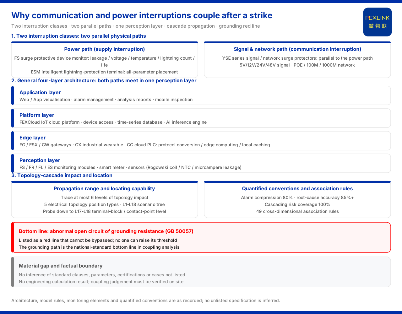
After a lightning strike, communication interruption and power-supply interruption often appear at the same time, and the site therefore easily treats both as one vague "the system is down". From the viewpoint of the monitoring system, these are not two mutually unrelated isolated faults but the result of the power path and the signal and network path being affected at the same time in one disturbance and interwoven in time. The general four-layer architecture of the monitoring system given by the product material places power-side monitoring and signal/network-side monitoring in the same perception layer, which is then aggregated by the same platform; this is both the architectural precondition for the two types of interruption possibly appearing together and coupling with each other, and the basis for the statement that "watching only one path cannot explain the on-site phenomenon".
The material also provides tools for studying the coupling and the direction of propagation. The topology-cascade impact capability can trace the range over which one event conducts through the electrical topology to several levels, and, together with the cross-dimensional association rules, it is used to analyse the relation and propagation path between interruptions. In other words, coupling is not an empirical judgement.
1. Why the two types of interruption are easily seen as one thing
Communication interruption and power-supply interruption are highly similar in phenomenon: the device goes offline, data stops, and alarms come up at the same time. If only the result is seen, the two are almost indistinguishable. But they correspond to two different physical paths — one is power supply, the other is signal and network transmission. That the material places these two kinds of monitoring modules in the same perception layer shows precisely that, in normal operation, they are two lines that exist in parallel and are collected separately; only when both are disturbed at the same time does the manifestation superimpose into "the whole system is down".
Confirming the two separately is the starting point for judging the direction of the fault. Only after confirming the respective states of the power side and the signal/network side can one judge which came first and which was caused by which. This is also why this article discusses the coupling at four levels: architecture, placement, propagation and bottom line.
2. The four-layer architecture: the two paths meet in the same perception layer
The general four-layer architecture given by the material consists of the perception layer, the edge layer, the platform layer and the application layer. The perception layer undertakes the front-end acquisition and contains monitoring modules, smart meters and sensors, among which there is both power-side monitoring and protection for the signal and network, and also such elements as Rogowski coils, NTC and microampere-level leakage sensors. The edge layer consists of the lightning-protection smart gateway, the edge-computing gateway, the industrial gateway, the industrial wearable and the cloud PLC, and undertakes protocol conversion, edge computing and local caching. The platform layer is the IoT cloud platform, containing device access, a time-series database and an AI inference engine. The application layer provides Web and App visualisation, alarm management, analysis reports and mobile inspection.
The key of this chain is that power monitoring and signal/network monitoring are in the same perception layer and are aggregated by the same platform. The two kinds of data are parallel at the source and merge on the platform. For this reason, if one lightning strike disturbs both paths at the same time, the interruptions appear in a coupled form rather than each going its own way.
3. The monitoring placements on the power path
The power-side monitoring placements are undertaken by two product classes.
The first is the FS surge protective device monitor (e.g. FS-00011-R). The model rule of the material encodes voltage channels, leakage-current channels, temperature channels, switching quantities and grounding/lightning-strike elements into positions, with the communication method listed separately. It can simultaneously monitor remote signalling, air-switch state, grounding state, lightning count, leakage current, temperature, voltage and life estimation. The key parameters include leakage current 50.0 to 1200.0μA (±10μA), voltage 0 to 400.0V (±0.1V), temperature -20 to 100℃ (±1℃), lightning count 0 to 9999 times (minimum trigger 0.1kA), and life estimation 0 to 100%. These parameters make it a monitoring placement for power-side lightning disturbance.
The second is the ESM intelligent lightning-protection monitoring terminal (e.g. ESM-21001-R), which the material calls an all-parameter monitoring placement. Its model rule encodes power, display, phase count, current parameters and version into positions: the power position distinguishes DC5V from AC220V, the display position distinguishes digital tube from OLED, the current-parameter position is 0.05 to 1.2mA, and the version distinguishes the basic four-element version from the flagship multi-element version. Its monitoring items cover switching quantities, grounding state, lightning count, leakage current, temperature, voltage, humidity and life estimation, more complete than the former.
Both power-side placements point to the same judgement: a power-supply interruption is not something that the single sentence "is there electricity or not" can cover. It can be decomposed and observed through leakage current, voltage, temperature, lightning count and life, thereby judging which section of the power path the disturbance occurred in.
4. The protection links on the signal and network path
The signal and network side likewise has matching protection links. The material lists the matching YSE series surge protective devices (e.g. YSE XM-H5), covering 5V, 12V, 24V and 48V signal surge protective devices, broadcast-signal surge protective devices, and POE, 100M and 1000M network surge protective devices, plus 220V, 24V and 12V network two-in-one surge protective devices. These links exist in parallel with the power path rather than as an accessory to power protection.
This parallel relation matters: the cause of a communication interruption may lie in the signal or network protection link, or may be conducted from a power-side problem. Only when each of the two paths has its own protection and monitoring links can they be located separately. If signal and network protection is regarded as a dispensable supplement, the direction may be misjudged when coupling occurs.
5. Coupling and propagation: topology-cascade impact and location
To explain "which came first" and "coupling", a propagation model and locating capability are needed. The topology-cascade impact engine in the material can trace at most 6 levels of topology impact, used to characterise the range over which one event conducts through the electrical topology to several levels. The engine maintains independent thresholds and risk models for the five electrical topological position types — point of common coupling, main distribution panel, distribution panel, feeder line and load terminal — and adopts an 18-level scenario positioning tree that can probe down to terminal-block level and contact-point level.
At the same time, the material gives quantified conventions such as alarm compression 80%, root-cause accuracy above 85%, scenario positioning precision reaching terminal-block and contact-point level, and cascading risk coverage 100%, and lists 49 cross-dimensional association rules. Together, these rules and the locating capability show that the coupling relation can be studied: to which levels an event conducts, at which level the symptom first appears, and in which link the root cause falls, all have corresponding analysis tools.
6. Bottom line: an abnormal open circuit of grounding resistance
Whatever the conclusion of the coupling analysis, one bottom line does not change. The material lists "an abnormal open circuit of grounding resistance" as a red line that cannot be bypassed, whose threshold no one can raise, with GB 50057 as the basis standard. The grounding path is therefore the national-standard bottom-line link in the coupling analysis of communication and power-supply interruption.
This also reminds us that the coupling analysis cannot stop only at the relations between paths but must also land on the common bottom line of grounding. Once grounding is open, any subsequent path analysis loses the foundation on which it stands. The red line cannot be relaxed precisely because it is the common precondition on which whether all paths can work normally depends.
Scope and limitations
First, this article explains only why communication interruption and power-supply interruption appear one after another and couple with each other; the factual boundary is limited to what the product material lists, and it introduces no standard clause, parameter, certification or case not listed.
Second, the four-layer architecture, the model rules, the monitoring elements and the various quantified conventions are all existing records of the material; this article does not infer the specifications of unlisted models from them, nor does it draw a conclusion about the interruption sequence at any specific site.
Third, the values of 80%, above 85%, 100% and at most 6 levels involved in the text are all conventions recorded by the material; this article does not expand them into a guarantee for any scenario.
Fourth, the determination of coupling and propagation must be verified in conjunction with the on-site scenario and equipment conditions; this article provides no engineering calculation result.


