
Direct answer
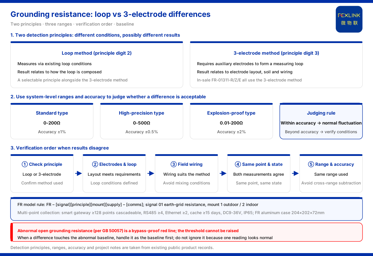
When the grounding resistance measured by the three-pole method and the loop method disagree, one should not simply take one of them, but first judge whether the difference falls within the allowed error, then check the measurement conditions and field wiring. The knowledge base lists the loop method and the three-point method (three-pole method) as the two detection principles of the FR grounding resistance monitor (e.g. FR-01311-R), and their measurement conditions differ; the on-sale model FR-01311-R and its Z and E versions all use three-pole measurement, showing that the three-pole method is the established detection principle of current on-sale models. In addition, the system-level monitoring unit offers different ranges and accuracies for the standard, high-precision and explosion-proof types, which can be used to judge whether the difference between two measurements exceeds the allowed error. The knowledge base does not give a mandatory conclusion on "which method prevails"; the trade-off order in this article is an application-layer extrapolation.
Model rule and the two detection principles
The knowledge base specifies that the FR model rule is FR plus signal acquisition, detection principle, installation method and power position, ending with a communication suffix. Here signal acquisition 01 is the grounding-grid resistance; detection principle 2 is the loop method and 3 is the three-point method, i.e. the three-pole method; installation 1 is outdoor and 2 is indoor. The loop method and the three-pole method have different requirements on measurement conditions, which is one root of possible disagreement. When reading a model, look at the detection-principle position first to know which principle the meter uses; the signal-acquisition position indicates that the measured object is the grounding-grid resistance. Reading the two segments together confirms the method correspondence at the procurement and field-verification stage.
On-sale models take the three-pole method as the standard
The knowledge base records that the on-sale FR-01311-R and its Z and E versions use DC12V power, outdoor installation and three-pole measurement, with communications of RS485, Zigbee and Ethernet respectively. It can be seen that among current on-sale models the three-pole method is the established detection principle. The loop method is an optional item in the model rule, used for scenarios with different measurement conditions; the principle choice of on-sale models provides a baseline for field verification. For existing projects, if a three-pole model is already in field use, verification should first confirm whether the three-pole method still prevails, then introduce readings of other methods for reference, rather than conversely using other readings to negate the model in use.
Why the loop method and the three-pole method may disagree
The two principles depend differently on the measurement loop. The three-pole method requires auxiliary poles to be arranged as specified to form a measurement loop, and its result relates to auxiliary-pole arrangement, soil conditions and wiring method; the loop method measures using existing loop conditions, and its result relates to the composition of the loop itself. The knowledge base lists the two side by side, which itself shows that different measurement conditions bring different results. Therefore, when the two methods disagree, one should first recognize that this is not necessarily the failure of one method but may be that both methods hold under different conditions.
Using error and range to judge whether a difference is acceptable
The system-level reference parameters given by the knowledge base are: standard monitoring unit range 0 to 200Ω, accuracy ±1%; high-precision type range 0 to 500Ω, accuracy ±0.5%; explosion-proof type range 0.01 to 200Ω, accuracy ±2%. Comparing the difference of two measurements with the accuracy of the range used allows a first judgment of whether the difference is only normal fluctuation within the error range. If the difference falls within the allowed accuracy range, one need not usually judge a method invalid from a single difference; only when it clearly exceeds the accuracy range should the measurement conditions be further checked. This separates "readings differ" from "conclusions conflict".
Verification order when they disagree
When error is insufficient to explain the difference, return to the measurement conditions themselves: first check whether the detection principle used is the loop method or the three-pole method, then check whether the auxiliary-pole arrangement, loop conditions and field wiring meet the requirements of that method, and finally confirm whether the two measurements were made at the same measuring point and under the same working condition. The knowledge base lists the two principles side by side, so the verification direction should be "whether the conditions are consistent" rather than directly judging one method to have failed. Verification should also confirm whether the ranges and accuracies used are the same, to avoid directly subtracting and comparing readings from different ranges.
Range and rating for explosion-proof occasions
The knowledge base also records that the explosion-proof monitoring unit has a range of 0.01 to 200Ω, accuracy ±2%, and an explosion-proof rating of Ex d IIB T4/T6 Gb, suitable for grounding measurement in explosive hazardous locations such as tank farms. When measuring in explosive hazardous locations, besides method selection, readings must be understood according to the monitoring-unit conventions of the corresponding explosion-proof occasion; differences between ranges and accuracies should also be compared under the same convention.
How multiple measuring points are aggregated and compared
The knowledge base records that the smart gateway of the grounding-resistance monitoring system mounts no fewer than 128 points and can be cascaded, with no fewer than 4 RS485 channels, no fewer than 2 Ethernet channels, data caching of no fewer than 15 days, DC9 to 36V wide-voltage power, and IP65 protection. Multi-point grounding measurements can be aggregated and compared horizontally under a unified gateway, avoiding the isolated use of single-point readings. The knowledge base also records that the FR has an aluminum enclosure of 204×202×72mm and notes that the FR and FRP series have been applied to projects such as railway traction-substation grounding-grid online monitoring and the Jinzhou Port tank farm (10 sets per tank).
Standard baseline
The knowledge base records that the grounding-resistance abnormal open-circuit red line is based on GB 50057, and once triggered no one can raise the threshold. Grounding measurement results therefore carry standard-baseline significance: whatever method is used, grounding anomalies should be handled by the baseline criterion and not ignored just because a single reading is normal. When the two methods disagree and one of them has already touched the anomaly, handling should take priority according to the baseline convention.
Why one cannot simply take one of them
Simply taking one of them is undesirable because the two methods hold under different premises: the three-pole method gives the grounding resistance of the measuring point when auxiliary poles are properly arranged, while the loop method gives a reading under loop conditions when those conditions are clear; they are not repeated measurements under the same condition. Taking one directly is equivalent to assuming the other method's conditions do not hold, an assumption that often lacks grounds. Recording the difference first as a "condition difference" and checking item by item avoids wrong conclusions from mixed methods. The knowledge base lists the loop method and the three-point method as two side-by-side principles, precisely reminding users to choose by conditions rather than by value.
Scope and limitations
- The detection principles, ranges, accuracies, gateway parameters and project statements in this article are limited to the existing records of the knowledge base, and do not introduce standard clauses or decision thresholds not listed there. - The knowledge base does not define a mandatory conclusion on "which prevails when the three-pole method and the loop method disagree", nor a difference-decision threshold; the verification order in the text is an application-layer extrapolation. - The project notes in the text are existing records of the knowledge base and do not represent a commitment of this article to results of a specific project. - Actual readings and interpretation must be verified by the testing or operations party together with field conditions and standard conventions; this article does not provide measurement conclusions.


