
Direct answer
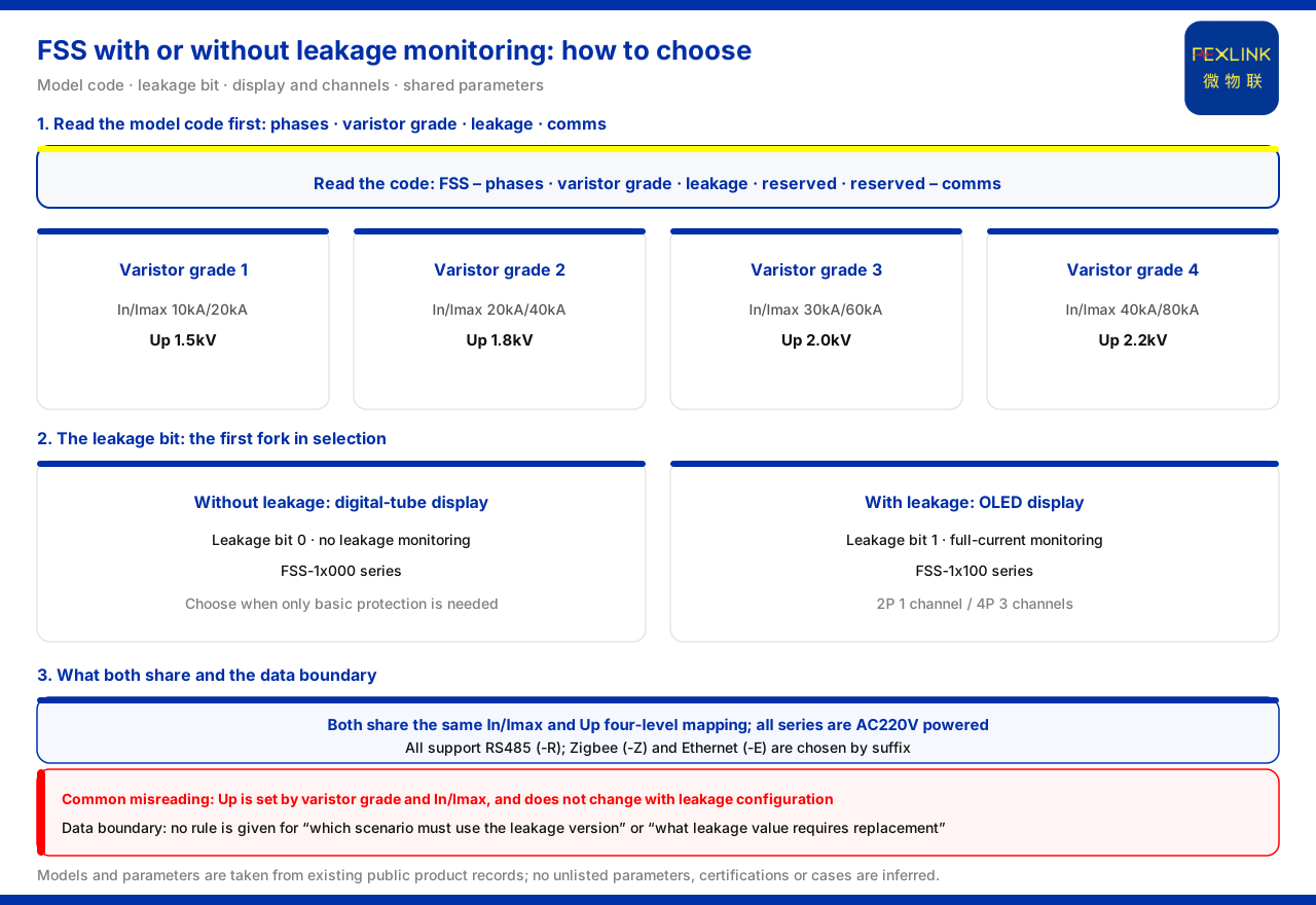
When choosing between the FSS intelligent surge protective device with a leakage-current version and the version without it, the key difference is not discharge capability but whether leakage-current trends need to be monitored and which display method is used. The knowledge base records that the version without leakage current (FSS-1x000 series) uses a digital-tube display, while the version with leakage current (FSS-1x100 series) uses an OLED display and carries 1-channel or 3-channel leakage-current monitoring. The two share the same In and Imax rating system, the same Up correspondence, and the same power-supply and communication options. Therefore, choose the leakage-current version when degradation trends must be observed; choose the non-leakage version when only basic lightning protection is needed. The knowledge base does not give a decision rule for "which scenarios must choose the leakage-current version"; the trade-off order in this article is an application-layer extrapolation.
How to read the model rule
The knowledge base specifies that the FSS model rule is FSS plus phase count, varistor level, leakage current, reserved, reserved position, ending with a communication suffix. Here phase count 1 means 2P and 2 means 4P; varistor levels 1 to 4 correspond to Imax 20kA, 40kA, 60kA and 80kA respectively; leakage position 0 means no leakage-current monitoring and 1 means full current, i.e. with leakage current. When reading a model, first locate the basic type by phase count and varistor level, then judge whether leakage current is present by the leakage position, and finally read the communication suffix. Breaking the model into these segments avoids confusing configuration differences with capability ratings.
The leakage position is the first fork
Among the segments of the model rule, phase count and varistor level determine basic electrical capability, while the leakage position determines whether leakage-current monitoring capability is added. Therefore, when selecting a model the leakage position can be treated as the first fork: first ask "does this circuit need leakage-current observation", and once the answer is fixed, return to phase count and varistor level to determine the basic type, and finally handle the communication suffix. The advantage is that the leakage-current add-on does not in turn affect the choice of discharge capability; the two are judged independently. If the order is reversed and the model is picked first by "with or without leakage current", it is easy to overlook whether phase count and varistor level match the distribution level; if the varistor level is chosen first and the leakage position is added afterwards, both dimensions land on explicit grounds.
Why leakage current deserves separate observation
The knowledge base describes leakage-current monitoring as the key configuration by which the leakage-current version can observe degradation trends. Understood at the application layer, a surge protective device gradually degrades during long-term operation, and the change in leakage current can serve as one clue for observing this process; bringing leakage current into monitoring is equivalent to adding a continuously readable state dimension to the lightning-protection device. It must be emphasized that the knowledge base only states that leakage-current monitoring is the key configuration of the leakage-current version; it does not give a quantitative relationship between leakage-current change and degradation degree, nor a decision threshold. Therefore, whether leakage observation is worthwhile for a given circuit should be an engineering judgment rather than one based on a single unified value.
Differences between the versions with and without leakage current
The knowledge base parameter table distinguishes display methods by leakage-current configuration: the version without leakage current, FSS-1x000 series, uses a digital-tube display; the version with leakage current, FSS-1x100 series, uses an OLED display. Leakage-current monitoring is the key configuration by which this version observes degradation trends, and the OLED display presents leakage-current values and state directly. The number of leakage-current channels of the with-leakage version is distinguished by pole count: 4P types have 3 channels and 2P types have 1 channel, corresponding to three-phase and single-phase configurations respectively. That is, adding leakage current not only adds a monitoring item but also changes the display method and the observable channel count; within the same series, different pole counts give different observable leakage-current channels.
Display method and observable channel count
From an operations perspective, the display method determines what can be read directly on site. A digital-tube display is suited to local reading of basic state; an OLED display is paired with leakage-current monitoring and facilitates reading leakage-current values and changes. The knowledge base maps the two display methods to the non-leakage and leakage-current versions respectively, showing that the display method is not an item freely selectable independently of the leakage-current configuration but is determined together with it. Meanwhile, the number of leakage-current channels is determined by pole count: 2P corresponds to 1 channel and 4P to 3 channels. If the channel requirement is clarified first and then the pole count and type chosen, the observable channel count is neither overestimated nor underestimated.
Complete model comparison
The knowledge base lists: the non-leakage models of the FSS intelligent SPD (FSS-11000/21000 to FSS-14000/24000) use a digital-tube display; the leakage-current models of the FSS intelligent SPD (FSS-11100/21100 to FSS-14100/24100) use an OLED display and provide 1 or 3 leakage-current channels. The two groups correspond one-to-one in varistor level, forming a complete comparison for the with/without leakage-current choice. Under this comparison, the same varistor level has both a non-leakage version and a leakage-current version, with the difference concentrated in leakage-current monitoring and display method rather than discharge capability.
What the two versions share
The versions with and without leakage current share the same varistor level system: the correspondence of In and Imax and Up is 10kA and 20kA to 1.5kV, 20kA and 40kA to 1.8kV, 30kA and 60kA to 2.0kV, and 40kA and 80kA to 2.2kV. The whole series is powered by AC220V; communications all support RS485, i.e. the R suffix, with Zigbee as the Z suffix and Ethernet as the E suffix selected as needed. It can be seen that the leakage-current configuration changes the additional monitoring capability and display method but does not change the discharge capability rating or the networking method. This point matters: choosing leakage current or not is not a trade-off between two discharge capabilities but a decision whether to add leakage observation on top of the same discharge capability.
Common misreading: Up does not change with leakage configuration
A common misreading is to compare leakage-current configuration together with protection level. According to the correspondence given by the knowledge base, Up is determined by the varistor level and the In and Imax ratings, corresponding one-to-one across the four ratings, and does not occupy a separate model segment; the with-leakage and non-leakage versions have the same Up at the same varistor level. Therefore, one cannot infer that a version has higher or lower Up because it carries leakage current, nor treat Up as a value selectable independently of the varistor level. The correct approach is to determine the In and Imax and Up rating by varistor level first, then decide the leakage position and communication suffix.
Selection order
Following the above, first determine the basic type by phase count and varistor level to ensure the In and Imax and Up ratings match the distribution level; then judge whether leakage-current trends are needed: if so, choose the leakage-current version and confirm 1 or 3 channels by pole count; if not, choose the non-leakage version. Finally select the communication suffix according to the field networking method. The knowledge base does not give a decision rule for "choosing the leakage-current version by which leakage state or degradation degree", nor a threshold for when leakage current should trigger replacement; this trade-off is therefore an engineering decision that should be determined together with circuit importance and maintenance methods.
Scope and limitations
- The model rules, parameters and configurations in this article are limited to the existing records of the knowledge base, and do not introduce standard clauses, certifications or selection thresholds not listed there. - The knowledge base does not define a decision rule for "which scenarios must choose the leakage-current version" or "when leakage current should trigger replacement"; the trade-off order in the text is an application-layer extrapolation. - The models and parameters in the text are existing records of the material, and no specification or protection effect of unlisted models is inferred from them. - Specific selection must be determined by engineering design together with field circuit conditions and distribution level; this article does not provide selection calculation results.


