
Direct answer
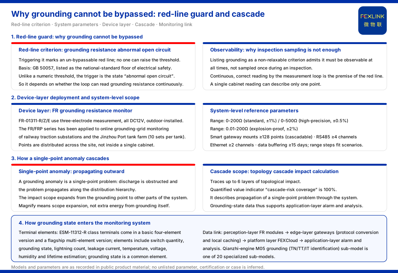
An abnormal grounding state magnifies the damage scope of a lightning strike, because grounding is the key path for discharging lightning energy. Among the red-line guards of the product material, one red line specifies that a "grounding resistance abnormal open circuit" triggers a determination that is un-bypassable and whose threshold no one can raise, based on GB 50057. This shows that grounding is not an optional compliance item but is listed as the national-standard floor of electrical safety. Once grounding is abnormal, energy discharge is obstructed and the problem propagates from the grounding point to other parts of the system; the topology cascade impact calculation, which can trace up to 6 layers with a cascade-risk coverage of 100%, is exactly what describes the propagation scope of such a single-point problem through the system.
1. Why grounding is listed as an un-bypassable red line
The red-line guard table of the product material writes "grounding resistance abnormal open circuit" as an un-bypassable red line, explicitly stating that no one can raise the threshold, based on GB 50057. Unlike a numeric threshold, the trigger condition of this red line is the state description "abnormal open circuit", so it depends more on whether the measurement loop can read the grounding resistance continuously and correctly. Listing grounding among the criteria that cannot be relaxed is equivalent to admitting that the grounding state must be observable at all times, rather than being sampled once during an inspection.
2. The range and system scope of grounding monitoring
The reference parameters given by the product material for the grounding resistance monitoring system are at system level rather than single-product level: the monitoring-unit range is 0-200Ω (standard type, ±1%), 0-500Ω (high-precision type, ±0.5%) and 0.01-200Ω (explosion-proof type, ±2%); the smart gateway mounts no fewer than 128 points (cascadable), with no fewer than 4 RS485 channels, no fewer than 2 Ethernet channels and no fewer than 15 days of data buffering. In addition to the range, it also specifies mounting capability, interfaces and buffering, which shows that the object being deployed is a cascadable grounding-grid monitoring system. The range steps correspond to different measurement scenarios, and the smaller lower limit of the explosion-proof type shows that flammable and explosive sites have a separate scope. Placing range, mounting capability, interfaces and buffering in one set of reference parameters is itself significant: these quantities describe a deployed grid rather than an isolated meter, and they are what allow scattered grounding points to be read as one system.
3. How grounding monitoring lands at the device layer
At device level, the product material records that the FR grounding resistance monitor (e.g. FR-01311-R) uses three-electrode measurement, and that the models FR-01311-R/Z/E are all DC12V and outdoor-installed; the FR/FRP series has been applied to projects such as online grounding-grid monitoring of railway traction substations and the Jinzhou Port tank farm (10 sets per tank). Outdoor installation and the "10 sets per tank" placement wording show that the object of grounding monitoring is grounding points scattered across the site, rather than a reading inside a single cabinet. The more points there are, the more likely a single-point anomaly is to be detected and located. A single cabinet reading can only describe one point; a set of points distributed over the site can show which of them has changed, and it is the comparison between points that turns a local measurement into a grid-level observation.
4. How a single-point anomaly cascades
The product material records that the topology cascade impact calculation of the Wanxiang engine can trace up to 6 layers of topological impact, and that among its quantified value indicators the "cascade-risk coverage" is 100%. Read on grounding, this wording means: a grounding anomaly is a single-point problem, but the impact analysis can extend downstream along the distribution hierarchy and cover the other parts associated with that grounding point. "Magnify" refers precisely to the impact scope expanding outward from the grounding point, not to the grounding itself generating additional energy. This is also why the grounding red line needs to be observable in real time rather than investigated after the fact.
5. How grounding state enters the monitoring system
The product material records that the ESM intelligent lightning-protection monitoring terminal (SPD monitor, e.g. ESM-11312-R) is divided into a basic four-element version and a flagship multi-element version, whose monitored elements include switch quantity, grounding state, lightning count, leakage current, temperature, voltage, humidity and lifetime estimation, among which grounding state is one of the common monitored elements. In the basic vital-signs sub-model of the Qianzhi engine, the same material lists M05 as the grounding (TN/TT/IT identification) sub-model, one of 20 specialized sub-models. On the data link, the perception layer contains the FR series monitoring modules, and the edge layer is borne by the lightning-protection smart gateway, the intelligent edge-computing gateway and the industrial gateway, which perform protocol conversion and local caching; the grounding-state data thus enters the platform layer and supports application-layer alarm and analysis. That grounding state appears both in the terminal elements and in the sub-model shows that it is a foundational dimension of parameter-level sensing. Its appearance at two levels means the same quantity is both acquired at the terminal and used by the model layer as an input to a dedicated sub-model, so grounding is not a one-off commissioning check but a continuously available element of the monitored state.
Scope and limitations
First, this article explains only why an abnormal grounding state magnifies the cascade impact; the factual boundary is limited to the product material, and no standard clause, parameter, certification or case not listed there is introduced.
Second, the product material gives no quantitative relationship between "what grounding resistance causes what damage"; "magnify" in this article is a general induction drawn from the listed red-line criteria, cascade trace-back layer count and cascade-risk coverage wording.
Third, the models and parameters in this article are all as recorded in the material; this article does not infer the specifications of unlisted models from them, nor does it make performance or effect inferences.
Fourth, the specific grounding monitoring scheme must be determined in conjunction with the on-site grounding-grid structure, soil conditions and grounding type; this article provides no determination or configuration calculation.


