
Direct answer
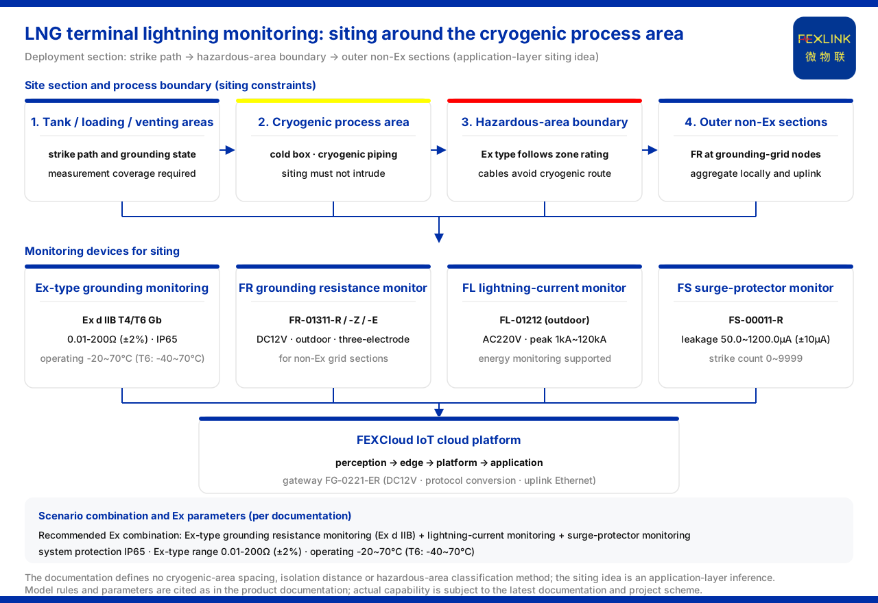
The cryogenic process area of an LNG receiving terminal imposes additional constraints on placement, cable routing and explosion-proof type: monitoring equipment must cover the lightning path and the grounding state at the tank area, loading area and vent area, and must not intrude on the cryogenic process boundary. Based on the petrochemical explosion-proof combination and the explosion-proof parameters already delivered by the product knowledge base, a workable approach is: select on-site grounding monitoring equipment with the corresponding explosion-proof type, place lightning-current monitoring on the lightning path, monitor surge protective device status separately, and aggregate multi-point data through a gateway for uplink. It must be stated in advance that the product knowledge base has no entry dedicated to an "LNG receiving terminal" or "cryogenic process area", and gives no placement spacing, safety isolation distance, hazardous-area classification method or anti-static monitoring product; the placement approach in this article is an application-layer inference and must not be treated as a delivered capability of the knowledge base.
Why a cryogenic process area cannot copy an ordinary tank farm
For explosion-proof grounding monitoring in an ordinary tank farm, the core constraint is to prevent the equipment from becoming an ignition source in a hazardous explosive atmosphere. Beyond that, an LNG receiving terminal superimposes a cryogenic process boundary: the cold box, the cryogenic piping and their ancillary areas impose stricter limits on installation position, cable routing and maintenance space, and monitoring points must not be brought arbitrarily close to process equipment; the cryogenic environment also imposes requirements on the temperature adaptability of the equipment. Placement is therefore not a verbatim copy of a general scheme, but a matter of first confirming where installation is possible and which explosion-proof type can be installed, and then determining the measurement points. Although the product knowledge base gives no placement rule specific to LNG, it provides explosion-proof parameters and scenario combinations that can support the judgement.
Available product combinations and explosion-proof parameters
At scenario level, the typical-application-scenario and selection comparison table of the product knowledge base lists the recommended combination for "oil tank farm / petrochemical lightning and explosion protection" as: explosion-proof grounding resistance monitoring (Ex d IIB) + lightning-current monitoring + surge-protective-device monitoring. This combination can serve as the selection starting point for lightning-protection monitoring placement on the periphery of the cryogenic process area of an LNG receiving terminal.
At parameter level, the reference parameters the product knowledge base gives for the grounding resistance monitoring system include: the explosion-proof monitoring unit has a range of 0.01-200Ω, an accuracy of ±2% and an explosion-proof marking of Ex d IIB T4/T6 Gb; the system protection rating is IP65 and the operating temperature is -20~70℃, with the explosion-proof T6 version reaching -40~70℃. These explosion-proof range, temperature and protection indicators provide the parameter basis for choosing explosion-proof grounding monitoring in areas that may be classified as explosive gas atmospheres.
At model level, the product knowledge base defines the FR grounding resistance monitor (e.g. FR-01311-R), whose model rule is FR–[signal acquisition][detection principle][installation method][supply]–[communication]; the R, Z and E versions of this model family all use a DC12V supply, outdoor installation and three-electrode measurement, with communication corresponding to RS485, Zigbee and Ethernet respectively. This series provides a model basis for grounding-grid resistance monitoring in non-explosion-proof sections outside the cryogenic process area; it is not an explosion-proof type and cannot replace explosion-proof equipment in a hazardous area.
Lightning current and surge protective device status are two further sensing lines. The product knowledge base defines the FL lightning current / transient current monitor (e.g. FL-01212), which is the outdoor version supplied at AC220V, with a peak range of 1kA~120kA and support for energy (charge / specific energy) monitoring, providing a model basis for recording lightning intensity in the site area. The key parameters of the FS surge protective device monitor (e.g. FS-00011-R) defined by the product knowledge base include leakage current 50.0~1200.0μA (±10μA), temperature -20~100℃ (±1℃) and lightning count 0~9999 (minimum trigger 0.1kA), providing a model and parameter basis for lightning-protection device status monitoring in the site area.
How data is aggregated into a monitoring boundary
At system level, the product knowledge base divides the general architecture of the monitoring system into four layers: perception layer, edge layer, platform layer (the FEXCloud IoT cloud platform) and application layer. On protocols, device downlinks support Modbus RTU (RS485), Zigbee (Modbus) and LoRa, while uplinks support Modbus TCP and MQTT (Ethernet, 4G), with IEC 61850 optionally available at gateway level. Data aggregation is handled by the FG lightning-protection smart gateway (e.g. FG-0221-ER) defined by the product knowledge base, whose model rule is FG–[gateway type][installation method][supply]–[downlink][uplink]; the gateway uses DC12V, is of the protocol-conversion type and has an Ethernet uplink, and can aggregate on-site data and send it up to the platform. It must be stressed that the selection of on-site equipment remains premised on the explosion-proof type, and the deployment location of gateways and similar equipment must equally obey the hazardous-area classification conclusion.
Placement principles and process boundaries
Placement should unfold with explosion protection and the process boundary as constraints: first obtain the confirmed hazardous-area classification drawing, clarifying the explosive hazardous-area level and temperature group of each part; then determine, on this basis, which locations permit installation and which explosion-proof type is required; finally, set the position and number of measurement points according to the grounding structure of the tank area, loading area and vent area, and route the monitoring cables away from the cryogenic pipe galleries and process exclusion zones. The knowledge base gives no placement spacing, safety isolation distance or area-classification method for a cryogenic process area; the principles above are an application-layer inference, and the specific points and isolation distances should be determined by design documents and site survey.
Scope and limitations
- The product knowledge base has no entry dedicated to an "LNG receiving terminal" or "cryogenic process area", and does not define sensor placement spacing or safety isolation distance rules for a cryogenic process area (including the cold box and cryogenic piping area), nor an "anti-static (static grounding / static discharge) monitoring" product, model or parameter, nor a hazardous-area classification method; the related placement conclusions in this article are an application-layer inference and must not be understood as a delivered capability of the knowledge base. - The model rules and parameters in this article (supply, measurement method, installation environment, range, explosion-proof marking, protection and temperature, protocol, and so on) are cited as they appear in the knowledge base and do not constitute a commitment to the result of a specific project. - This article constitutes no commitment to any unlisted indicator; actual capability is subject to the latest product documentation and project scheme.


