
Direct answer
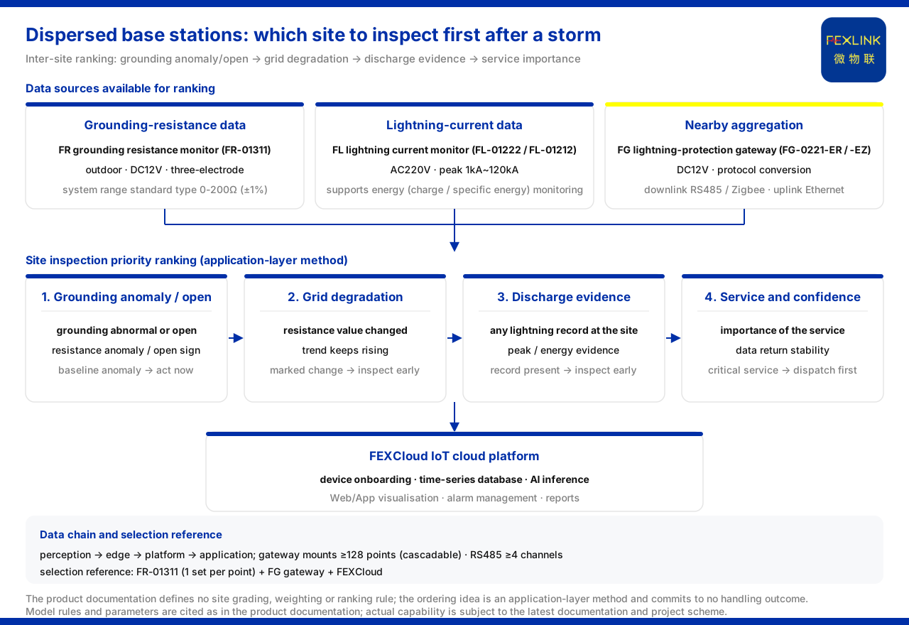
After a thunderstorm, dispersed base stations cannot possibly be inspected by manpower all at once. The reasonable approach is not "visit every station" but "first put the sites in an order", giving priority to sites that genuinely had a discharge event, whose grounding state shows an anomaly, and which carry critical services. It must be said in advance that this ordering is an application-layer recomputable reading procedure of this article; the product knowledge base does not give a ready-made rule for "base-station risk scoring" or "which station to inspect first after a thunderstorm". What it can provide is the model capability and system-parameter basis that support the judgement. The sections below first set out the data sources usable for ordering, then give one recomputable ordering approach.
Why dispersed base stations are hard to queue by feel
Thousands of base stations are distributed across different areas, alarms cluster after a thunderstorm, and operations manpower is limited. If inspection rotates by region, manpower is consumed equally across sites whose risk is not equal. To order sites, the premise is that every site has data that can be compared across sites: whether the grounding state has changed, whether a lightning strike really occurred, and whether the data can be returned reliably. Without such data, ordering can only be by feel. The difficulty is therefore not a shortage of manpower alone but the absence of a common measure; a queue is only meaningful when the stations in it can be placed on the same scale.
The data basis available for ranking sites
The first class is grounding-resistance data. The product knowledge base defines the FR grounding resistance monitor (e.g. FR-01311), whose model rule is FR–[signal acquisition][detection principle][installation method][supply]–[communication], where signal acquisition 01 denotes grounding-grid resistance, detection principle 2 is the loop method and 3 the three-point method, and installation 1 is outdoor and 2 indoor. The R, Z and E versions of this model family all use a DC12V supply, outdoor installation and three-electrode measurement, with communication corresponding to RS485, Zigbee and Ethernet respectively. This provides a model basis for online grounding-resistance monitoring of each station's grounding grid in a dispersed base-station network.
The second class is lightning and lightning-current data. The product knowledge base defines the FL lightning current / transient current monitor (e.g. FL-01222, FL-01212), whose model rule is FL–[detection range][channel count][function][installation method][supply]–[communication]; detection range 0 is 1kA~120kA and 1 is 0.1kA~1kA; function 1 is peak, 2 is peak plus energy, 3 is waveform and 4 is waveform plus energy. Both its indoor and outdoor versions use AC220V, have a peak range of 1kA~120kA, and support energy (charge / specific energy) monitoring. This can provide a data source for comparing the frequency and strength of lightning strikes at each station after a thunderstorm.
The third class is nearby aggregation of data. The product knowledge base defines the FG lightning-protection smart gateway (e.g. FG-0221-ER), whose model rule is FG–[gateway type][installation method][supply]–[downlink][uplink], where gateway type 01 is transparent transmission and 02 is protocol conversion. Both downlink versions of this gateway use DC12V, are of the protocol-conversion type, and have an Ethernet uplink, with downlinks corresponding to RS485 and Zigbee respectively. Such a gateway can take on the nearby aggregation and return of grounding and lightning data from multiple measurement points at dispersed base stations.
How the data joins into one chain
At the system level, the product knowledge base divides the general architecture of the monitoring system into four layers: perception layer, edge layer, platform layer and application layer. The perception layer includes the various monitoring modules; the edge layer is the gateway; the platform layer is the FEXCloud cloud platform, with device onboarding, a time-series database and an AI inference engine; the application layer provides Web/App visualisation, alarm management, analytical reports and mobile inspection. In the typical-scenario selection comparison, the recommended combination for online grounding-grid monitoring of substations and traction substations is "one set of grounding resistance monitor per point plus lightning-protection smart gateway plus FEXCloud". This data path can be reused for point-by-point grounding monitoring of dispersed base stations.
On the uplink side, the communication protocol matrix of the product knowledge base specifies that device downlinks support Modbus RTU (RS485), Zigbee (Modbus) and LoRa, while device uplinks support Modbus TCP and MQTT (Ethernet, 4G), with IEC 61850 optionally available at gateway level. This provides a protocol-layer basis for the uplink aggregation of multi-measurement-point data.
For system-level parameters, the reference parameters the knowledge base gives for the grounding resistance monitoring system include: the monitoring-unit range is divided into the standard type 0-200Ω (±1%), the high-precision type 0-500Ω (±0.5%) and the explosion-proof type 0.01-200Ω (±2%); the smart gateway mounts no fewer than 128 points and can be cascaded, provides no fewer than 4 RS485 channels and no fewer than 2 Ethernet channels, offers 4G, 5G and LoRa as options, buffers no fewer than 15 days of data, is supplied at DC9-36V wide voltage, and has a protection rating of IP65. The gateway's mounting and multi-channel uplink capability provides a system-level basis for the centralised aggregation of regional multi-base-station grounding-grid data.
A recomputable reading order (a recomputable reading procedure)
Given the data above, thunderstorm-aftermath inspection can be organised by the idea of "exclude first, subdivide afterwards": first look at which stations show an abnormal grounding resistance or signs of an open circuit, then look at which stations recorded stronger or more frequent discharges in the same thunderstorm, and finally combine this with the business importance of the station to decide the order of handling. It must be stressed again that this step is application-layer reading inference; the product knowledge base gives no site grading, weights or ordering algorithm. What it can provide is the model capability, system parameters and protocol paths listed above. The actual ordering rule should be determined by the operations party in conjunction with its own data and business criteria.
Scope and limitations
- The product models, parameters and system capabilities in this article are all based on the existing statements of the product knowledge base, and are not extended to base-station-specific entries, site grading rules or inspection ordering algorithms not listed in the knowledge base. - The product knowledge base does not define methods, criteria or thresholds for "base-station risk scoring", "inspection priority ordering" or "which station to inspect first after a thunderstorm", nor does it give the weighting rules needed for site ordering; the ordering idea in this article is application-layer reading inference and must not be understood as a delivered capability of the knowledge base. - The model rules and parameters in this article (supply, measurement method, installation environment, range, mounting point count, protocol and protection rating, and so on) are cited as they appear in the knowledge base and do not constitute a commitment to the result of a specific project. - This article constitutes no commitment to any unlisted indicator; actual capability is subject to the latest product documentation and project scheme.


