
Grounding-grid monitoring for photovoltaic power stations: which fails first, module grounding or the station grounding grid
Direct answer
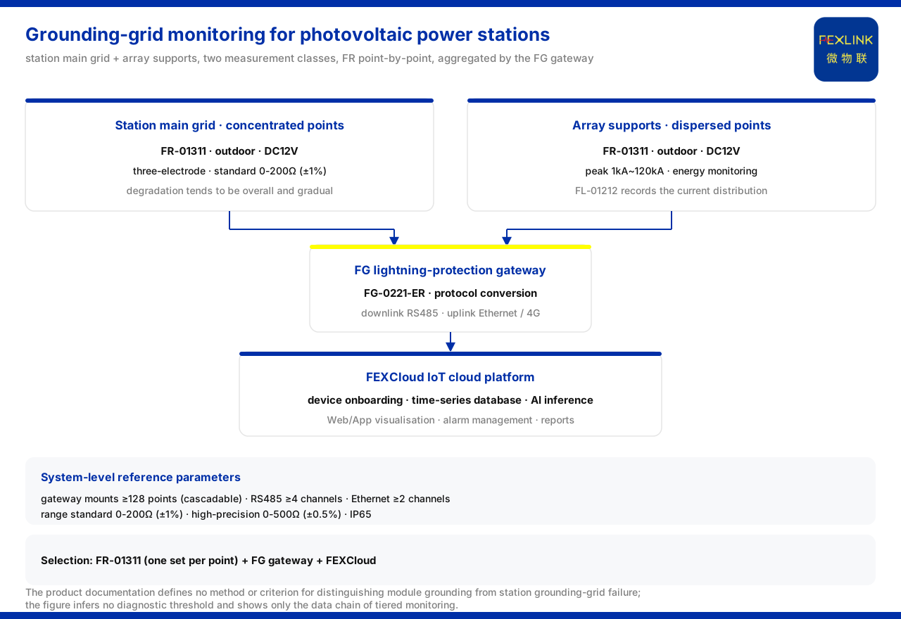
The grounding points of a photovoltaic power station fall roughly into two classes: the grounding points of the station's main grounding grid and the grounding points of the array module supports. The two classes serve in different environments and degrade differently, and operations often finds it hard to judge whether an anomaly comes from a local support grounding or from overall grounding-grid degradation. The path given by the product knowledge base is: use the FR grounding resistance monitor (e.g. FR-01311) to monitor the station's main grounding grid and the array-support grounding points separately, point by point, and use the FL lightning current / transient current monitor (e.g. FL-01212) to record the current distribution after a lightning strike; the two data classes are aggregated and uplinked to the cloud platform through the FG lightning-protection smart gateway (e.g. FG-0221-ER), thereby separating the local from the overall and guiding zoned remediation rather than whole-station treatment. It should be noted that the product knowledge base contains no dedicated entry for photovoltaic power stations or module-support grounding, and defines no method or criterion for distinguishing failures; this article does not infer diagnostic thresholds and explains only how the general models and system parameters carry this class of tiered monitoring.
Why the two classes of grounding points behave differently
The station's main grounding grid covers a large area with concentrated grounding points, and its degradation is more likely to appear as an overall gradual change; the array-support grounding points are numerous and dispersed across the station, and an anomaly is more likely to be local. If judged from a single overall measurement, the two kinds of problem are mixed together, which easily leads to an all-or-nothing remediation decision. To judge them separately requires a monitoring means that can be deployed point by point, recorded separately and aggregated uniformly. The two failure modes differ in spatial scale as well as in time scale, so a measurement that does not distinguish points cannot separate them.
The grounding-grid state data for zoned monitoring
The product knowledge base specifies the model rule of the FR grounding resistance monitor as: FR plus signal acquisition, detection principle, installation method and supply, then communication. In the detection principle, the loop method is coded 2 and the three-point method 3; in the installation method, outdoor is coded 1 and indoor 2; signal acquisition 01 denotes grounding-grid resistance. The three variants of the FR grounding resistance monitor (FR-01311-R/Z/E) all use a DC12V supply, an outdoor installation and the three-electrode measurement method, with communication of RS485, Zigbee and Ethernet respectively. The product knowledge base uses a deployment of one set per point for online grounding-grid monitoring, and this basis allows monitoring units to be deployed separately for the station's main grounding grid and for the array-support grounding points. Deploying at each class of point is what makes the two records comparable rather than merged.
The current distribution after a lightning strike
The product knowledge base defines the model rule of the FL lightning current / transient current monitor as: FL plus detection range, channel count, function, installation method and supply, then communication. Detection-range position 0 denotes 1kA~120kA and position 1 denotes 0.1kA~1kA; function position 1 denotes peak, 2 denotes peak plus energy, 3 denotes waveform, and 4 denotes waveform plus energy. In the model table, FL-01222 is the indoor variant and FL-01212 the outdoor variant; both use an AC220V supply, have a peak range of 1kA~120kA, and support energy monitoring. Such records reflect the current distribution of the array and station grounding systems after a lightning strike. The distribution matters because a strike couples into the grounding system through several paths, and recording where the current appears helps relate an event to the grounding points it passed through.
How the data is aggregated and uplinked
The product knowledge base specifies the model rule of the FG lightning-protection smart gateway as: FG plus gateway type, installation method and supply, then downlink and uplink; gateway type 01 is transparent transmission and 02 is protocol conversion. Both variants of the FG intelligent lightning-protection gateway (FG-0221-ER/EZ) use a DC12V supply, are of the protocol-conversion type, and have an Ethernet uplink, with RS485 and Zigbee downlinks respectively; they can serve as gateway options for aggregating and returning grounding data from multiple measurement points. The communication protocol matrix further lists: device downlink supports Modbus RTU (RS485), Zigbee (Modbus) and LoRa; device uplink supports Modbus TCP and MQTT (Ethernet, 4G), with IEC 61850 optionally available at gateway level. As a result, the data of the two classes of measurement points, station and array, can be aligned on the same platform by point and by time.
System-level support for multiple measurement points
In the grounding resistance monitoring system reference parameters given by the product knowledge base, the monitoring-unit range is divided into three tiers: standard type 0-200 Ω (±1%), high-precision type 0-500 Ω (±0.5%) and explosion-proof type 0.01-200 Ω (±2%); the system protection rating is IP65, the operating temperature is -20 to 70 °C, and the explosion-proof T6 variant is -40 to 70 °C. The smart gateway can mount no fewer than 128 points and can be cascaded, provides no fewer than 4 RS485 channels and no fewer than 2 Ethernet channels, offers 4G, 5G and LoRa as options, buffers no fewer than 15 days of data, is supplied at DC9-36 V wide voltage, and has a protection rating of IP65. The gateway's ability to mount no fewer than 128 points provides a system-level basis for the tiered monitoring of multiple measurement points across a photovoltaic station.
Architecture and selection combination
The product knowledge base divides the general monitoring system architecture into four layers: the perception layer (various monitoring modules) feeds through the edge-layer gateway (which performs protocol conversion, edge computing and local buffering) into the platform layer (the cloud platform's device onboarding, time-series database and AI inference engine), and then serves the application layer with Web and App visualisation, alarm management, analytical reports and mobile inspection. Its selection comparison table lists the recommended combination for "substation / traction substation grounding-grid online monitoring" as FR-01311 (one set per point) together with the FG lightning-protection smart gateway and the cloud platform. On this basis, this article explains the composition of the data chain for the tiered monitoring of a photovoltaic station area.
Scope and limitations
First, this article only restates content listed in the product knowledge base and introduces no standard clause, parameter, certification or case that is not listed.
Second, the model rules, the supply, installation, measurement method and communication of the three FR-01311 variants, the installation, supply, range and energy monitoring of the two FL variants, the downlink, uplink and protocol support of the two FG variants, and the system-level range, protection, temperature and buffering parameters are all bases listed in the product knowledge base.
Third, the scenario comparison table of the product knowledge base has no dedicated row for photovoltaic power stations or module-support grounding, and it defines no method, criterion or criterion threshold for distinguishing module grounding from station grounding-grid failure. The tiered diagnostic decision and the zoned remediation conclusion in this article are application-layer reasoning and must not be presented as delivered capabilities of the product knowledge base.
Fourth, this article describes a data acquisition and aggregation method and does not replace the design, inspection or compliance judgement of a specific project; the actual configuration must be confirmed in conjunction with on-site conditions and the latest product documentation.


