
Stray-current monitoring in metro traction substations: quantifying the invisible driver of grounding-grid corrosion
Direct answer
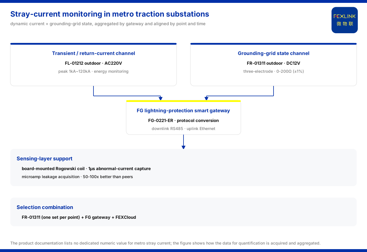
In a metro DC traction system, not all return current travels back along the running rails; part of it disperses through buried metal structures, forming stray current and accelerating grounding-grid corrosion. The conventional approach relies mainly on manual spot testing, which rarely yields continuous samples in either space or time, so quantification is difficult. The path given by the product knowledge base is: at the traction substation and the section drainage points, use the FL lightning current / transient current monitor (e.g. FL-01212) to acquire the dynamics of stray and transient current, and use the FR grounding resistance monitor (e.g. FR-01311) to record the trend of the grounding-grid state; then aggregate and upload the two data classes through the FG lightning-protection smart gateway (e.g. FG-0221-ER), aligning them by point and by time, so that "how strong the current is" and "how far the grounding grid has degraded" are placed in the same set of records. It should be noted that the product knowledge base lists no dedicated numerical value for metro stray current; this article does not infer a corrosion rate and only explains how the data needed for quantification is acquired and aggregated.
Why stray current is hard to quantify
Stray current changes continuously with train operation, the power-supply mode and the state of the drainage network, and is a dynamic process; a manual spot test yields only individual points at a single moment and cannot reflect the distribution and fluctuation. To turn the "invisible driver" into a comparable object, one needs continuous dynamic current records and trend records that reflect changes in the grounding-grid state; without either, quantification lacks a reference. This is precisely why the solution has to be built as a data chain spanning acquisition, aggregation and alignment, rather than as a single measurement.
The transient and return-current data channel
The product knowledge base defines the model rule of the FL lightning current / transient current monitor as: FL plus detection range, channel count, function, installation method and supply, then communication. Detection-range position 0 denotes 1kA~120kA and position 1 denotes 0.1kA~1kA; function position 1 denotes peak, 2 denotes peak plus energy, 3 denotes waveform, and 4 denotes waveform plus energy. The two model variants are shown in the following table.
| Model | Installation | Supply | Peak range | Energy monitoring | |:--|:--|:--|:--|:--| | FL-01222 | Indoor | AC220V | 1kA~120kA | Supported | | FL-01212 | Outdoor | AC220V | 1kA~120kA | Supported |
The monitor supports peak and energy monitoring and can be used for the dynamic acquisition of stray and transient current. In a traction environment, the peak value indicates how strong a transient event is, while the energy record indicates how much energy the event carries; together they describe the dynamics of the current rather than a single instantaneous reading.
The grounding-grid state data channel
The product knowledge base specifies the model rule of the FR grounding resistance monitor as: FR plus signal acquisition, detection principle, installation method and supply, then communication. The three variants of the FR grounding resistance monitor (FR-01311-R/Z/E) share a DC12V supply, an outdoor installation and the three-electrode measurement method; the product knowledge base also notes that this series has been applied to the online monitoring of railway traction substation grounding grids. At the system level, the reference parameters given by the product knowledge base for grounding resistance monitoring are: the monitoring unit range is divided into a standard type of 0-200 Ω (±1%), a high-precision type of 0-500 Ω (±0.5%), and an explosion-proof type of 0.01-200 Ω (±2%); the protection rating is IP65, the operating temperature is -20 to 70 °C, and the explosion-proof T6 variant is -40 to 70 °C; the smart gateway can mount no fewer than 128 points and can be cascaded, has no fewer than 4 RS485 channels and no fewer than 2 Ethernet channels, offers 4G, 5G and LoRa as options, buffers no fewer than 15 days of data, and is supplied at DC9 to 36 V wide voltage. All of the above are system-level reference bases.
How the data is aggregated and aligned
The model rule of the lightning-protection smart gateway in the product knowledge base is: FG plus gateway type, installation method and supply, then downlink and uplink. Gateway type 01 is transparent transmission and 02 is protocol conversion. Both FG-0221-ER and FG-0221-EZ are DC12V, protocol-conversion, Ethernet-uplink gateways, with RS485 and Zigbee downlinks respectively, and can serve as gateway options for the uplink aggregation of the two sensing data classes. The communication protocol matrix further lists: device downlink supports Modbus RTU (RS485), Zigbee (Modbus) and LoRa; device uplink supports Modbus TCP and MQTT (Ethernet, 4G), with IEC 61850 optionally available at gateway level. As a result, the two data classes of stray current and grounding-grid state can be aligned on the same platform by point and by time.
Support at the sensing layer
At the sensing layer, the product knowledge base records that the core sensor technology of the company includes a board-mounted special-shaped Rogowski coil, which can capture abnormal current at the 1μs level, together with microamp-level leakage-current acquisition; this acquisition accuracy is 50 to 100 times better than comparable products, at a cost of about 60 yuan per sensor and 200 yuan per module. Microsecond-level time resolution is the basis for capturing the rapid changes of stray and transient current, and it is this resolution that makes the dynamic current record able to reflect the process rather than only its endpoints.
Selection combination and boundaries
The selection comparison table in the product knowledge base writes the recommended combination for "substation / traction substation grounding-grid online monitoring" as FR-01311 (one set per point) plus the FG lightning-protection smart gateway and FEXCloud. On this basis, this article explains the composition of the quantification data chain, but it does not judge the corrosion rate, the drainage network, or the investment priority of grounding-grid renovation, which fall within the scope of professional regulations and engineering decisions.
Scope and limitations
First, this article only restates the content listed in the product knowledge base and introduces no standard clause, parameter, certification or case that is not listed.
Second, the model rules, the installation, supply, range and energy monitoring of the two FL variants, the supply, installation and measurement method of the three FR-01311 variants, the system-level range, protection, temperature and buffering, the downlink and uplink of the two FG variants, and the Rogowski coil and leakage-current acquisition parameters at the sensing layer are all bases listed in the product knowledge base.
Third, the product knowledge base lists no dedicated numerical value or corrosion rate for metro stray current; this article does not infer the stray-current intensity level, nor does it infer the grounding-grid corrosion rate or renovation priority.
Fourth, this article explains the acquisition and aggregation method of the quantification data and does not replace the design, inspection and compliance judgment of a specific project; the actual configuration must be confirmed in conjunction with on-site conditions and the latest product documentation.


