
Direct answer
Protective grounding, working grounding and lightning-protection grounding are three classes distinguished by purpose. Whether they may share the same grounding electrode is a judgement of system design and of the equipotential scheme, and the product material gives no unified conclusion: the material does not directly state the definitions of the three classes, their classification relationship or a shared-electrode requirement, nor does it give grounding-electrode materials, grounding-grid topology, step-voltage and touch-voltage limits, or target resistance tiers for each. What the material can establish is another thread: grounding is an object of continuous monitoring, and an abnormal open circuit of grounding resistance is listed as a non-bypassable safety red line, with GB 50057 as its basis.
1. What the material can establish: grounding is a monitored state
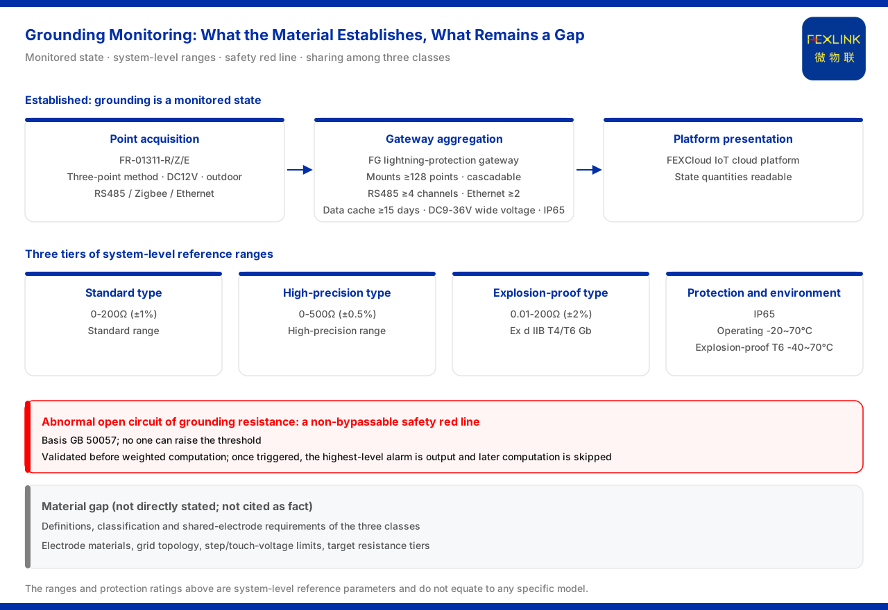
The landing point the product material gives for grounding is not a classification table but the treatment of grounding state as a monitorable item. The model rule of the FR grounding resistance monitor (for example FR-01311-R) encodes signal acquisition, detection principle, installation method and supply into field positions, with the detection principle divided into the loop method and the three-point method and the installation method into outdoor and indoor. The models FR-01311-R/Z/E all use the three-point method, DC12V and outdoor installation, with communication corresponding to RS485, Zigbee and Ethernet respectively. Seen from the monitoring perspective, grounding has to answer what the grounding-grid resistance is and whether the grounding path holds.
2. Separate or shared is a design judgement; the material gives no single answer
Whether the three classes of grounding may share one grounding electrode depends on the system design and the equipotential scheme. The material does not directly state the definitions and classification relationship of the three classes, nor does it give the concrete requirements for a shared grounding electrode. It therefore cannot be used as a material conclusion that a given class of grounding must be independent or that all three must be shared. How to choose in engineering should return to the applicable standards and the design conditions for judgement. The absence of a direct statement is itself meaningful: the material documents the monitoring products and their criteria, not a general theory of grounding classification, so a reader should not treat a particular sharing arrangement as endorsed or prohibited by it.
3. The system-level ranges of grounding resistance have three tiers
At the system level, the reference ranges the material gives for grounding-resistance monitoring fall into three tiers: standard type 0-200Ω (±1%), high-precision type 0-500Ω (±0.5%), and explosion-proof type 0.01-200Ω with explosion-proof rating Ex d IIB T4/T6 Gb (±2%); the protection rating is IP65, the operating temperature is -20~70℃, and the explosion-proof T6 version is -40~70℃. That the explosion-proof type is listed as a separate tier shows that hazardous environments have a dedicated range and environmental specification for grounding monitoring, and the parameters of the ordinary tiers cannot substitute for them. The three tiers therefore describe the range and accuracy that can be covered under different conditions, rather than three grades of one acceptance limit.
4. Grounding state is not only resistance: type identification and time-series trend
The material brings grounding into the basic vital-sign analysis, including grounding-type identification, that is, distinguishing the system grounding type as TN, TT or IT; at the same time it uses trend drift and a 0 to 100 time-series risk score as decision dimensions. This shows that grounding monitoring goes beyond a single-point resistance value and also includes type identification and a judgement of the trend over time; a single reading does not constitute a complete conclusion.
5. An abnormal open circuit of grounding resistance is a red line that cannot be bypassed
The material lists an abnormal open circuit of grounding resistance as a non-bypassable safety red line, with GB 50057 as its basis, and no one can raise the threshold. This criterion is validated before the weighted computation is carried out: once triggered, it outputs the highest-level alarm and skips the subsequent computation. This means that grounding state is a national-standard floor, not a negotiable operating parameter.
6. Landing on scenarios: online grounding-grid monitoring and explosion-proof configuration
The material lists online monitoring of substation and traction substation grounding grids as a recommended scenario, with the combination of the FR grounding resistance monitor (one set per point) together with the lightning-protection smart gateway and a cloud-platform-side service; the grounding grid is distributed in points, one set per point, and then aggregated and uplinked through the gateway. The system-level smart gateway supports mounting ≥128 points and can be cascaded, provides ≥4 RS485 channels and ≥2 Ethernet channels, optionally offers 4G, 5G or LoRa, caches data for ≥15 days, and uses DC9-36V wide voltage with IP65 protection. Another type of scenario is lightning and explosion protection in oil-tank farms and petrochemicals, with the combination of explosion-proof grounding resistance monitoring, lightning-current monitoring and lightning-protection device monitoring, corresponding to a differentiated configuration in hazardous environments.
Applicability and limits
First, this article explains only what the grounding-monitoring material can establish and why the question of sharing among the three classes of grounding cannot be answered directly by the material; its factual boundary is limited to the product material, and it introduces no standard clause, parameter, certification or case that is not listed.
Second, the definitions of the three classes of grounding, their classification relationship, the shared-electrode requirement, and the grounding-electrode materials, grounding-grid topology, step-voltage and touch-voltage limits and target resistance tiers for each, are not directly stated by the material; this article explicitly lists them as material gaps and does not cite them as facts.
Third, the 0-200Ω (±1%), 0-500Ω (±0.5%) and 0.01-200Ω (±2%, Ex d IIB T4/T6 Gb) cited here are all system-level reference parameters; this article does not equate them with the specification of any specific model, nor does it judge on that basis whether on-site grounding is acceptable.
Fourth, the reference to GB 50057 for the grounding red line is limited to the related criterion in the material and does not expand its specific clauses; actual grounding design should be subject to on-site conditions and the applicable standards.


