
Direct answer
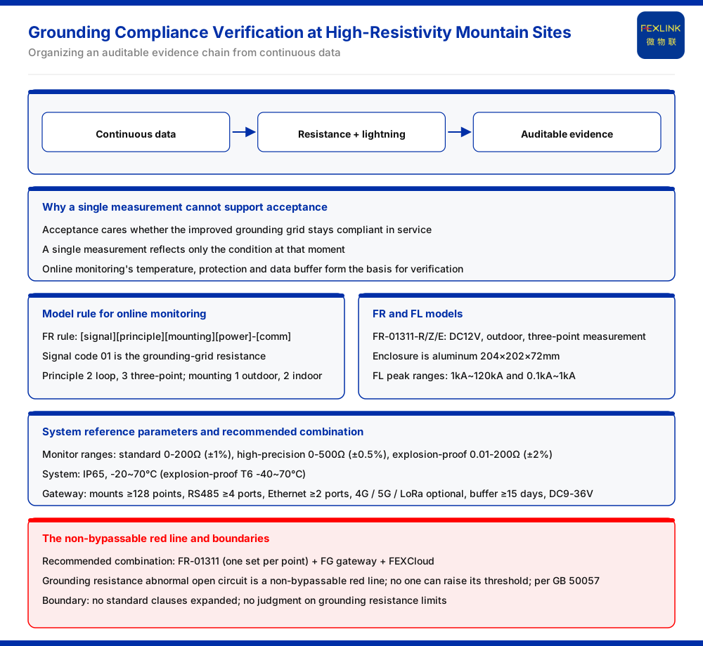
At a site in mountainous terrain with high soil resistivity, the key to compliance verification after a grounding retrofit is not whether "a single measurement passes" but whether continuous data can describe the state over a period of time. The grounding resistance monitor (FR) given by the product knowledge base supports outdoor installation and three-point measurement; its recommended combination is FR-01311 at 1 set per point plus the FG lightning-protection smart gateway and FEXCloud. The system reference parameters also include IP65 protection, an operating temperature of -20 to 70℃ (the explosion-proof T6 version -40 to 70℃) and a data cache of not fewer than 15 days, which are described as the data-retention and deployment preconditions for all-season online compliance verification. On this basis, the lightning current / transient current monitor (FL) can correlate the response under a surge, forming a reviewable evidence chain.
Why a single measurement cannot support acceptance
In a mountainous high-soil-resistivity scenario, what acceptance cares about is whether the retrofitted grounding grid can remain compliant during operation, whereas a single measurement can only reflect the state at the moment it was taken. To give a conclusion covering different states at the acceptance stage, the measurement has to be extended from a one-off action to a period of time. The fact that the product knowledge base lists the temperature range, protection rating and data cache among the online-monitoring parameters is precisely what supplies the precondition for such continuous verification. A one-off reading carries no information about how the state changed between readings, so it cannot show whether compliance held throughout. The temperature range widens the window over which the state can be read, the protection rating fixes the environment in which the reading equipment can be installed, and the data cache determines how long a record survives; each of these supports the same goal of turning a single point into a period.
The landing point of online monitoring
The model rule of the grounding resistance monitor is: FR followed by signal acquisition, detection principle, installation and supply, and then the communication suffix. Signal acquisition 01 is the grounding-grid resistance; detection principle 2 is the loop method and 3 is the three-point method; installation 1 is outdoor and 2 is indoor. The three models FR-01311-R/Z/E listed by the product knowledge base are all DC12V supply, outdoor installation and three-point measurement, with an aluminum housing of 204×202×72 mm, and the entry notes that they have been applied to railway traction substation grounding-grid online monitoring.
Using the surge response to cover the other side
Reading the grounding resistance continuously reflects a static state. A lightning strike is a transient process, and the FL lightning current / transient current monitor given by the product knowledge base divides its peak range into two tiers, 1kA~120kA and 0.1kA~1kA; FL-01222-R/Z/E is the indoor type and FL-01212-R/Z/E is the outdoor type, and both are AC220V supply with a peak of 1kA~120kA and support energy monitoring. Only by looking at the surge current together with the grounding-grid state can both the static and the transient layers be covered. The two instruments answer different aspects of the same event: one describes the continuing state of the grid, the other the momentary stress applied to it.
System reference parameters and the recommended combination
At the monitoring-unit level, the product knowledge base gives reference range tiers: standard type 0-200Ω at an accuracy of ±1%; high-precision type 0-500Ω at an accuracy of ±0.5%; and explosion-proof type 0.01-200Ω at an accuracy of ±2%. At the system level it gives a protection rating of IP65, an operating temperature of -20 to 70℃ and -40 to 70℃ for the explosion-proof T6 version, a smart gateway mounting not fewer than 128 points (cascadable), RS485 not fewer than 4 channels, Ethernet not fewer than 2 channels, 4G, 5G and LoRa optional, a data cache of not fewer than 15 days, DC9 to 36V wide voltage, and IP65. These parameters are described as providing the data retention and deployment preconditions for all-season online compliance verification. For typical applications, the recommended combination for substation and traction substation grounding-grid online monitoring is FR-01311 (1 set per point) plus the FG gateway and FEXCloud. The unit-level tiers state which amplitude range the measurement covers, while the system-level figures state the conditions under which those measurements can be gathered continuously; the recommended combination is what ties the two together for the named scenario.
A red line that cannot be bypassed
The product knowledge base lists "grounding resistance abnormal open circuit" as a red-line rule that cannot be bypassed, and notes that no one can raise its threshold, with GB 50057 as the governing standard. This red line does not take part in weighted dilution among indicators. Because it does not enter the weighted comparison, it cannot be offset by otherwise favourable readings elsewhere; it stands as a precondition rather than one indicator among several. Seen together with the monitoring capability described above, the requirement that the path must hold is a precondition of the acceptance evidence, not a negotiable indicator.
Scope and limitations
First, this article restates only what the product knowledge base lists, and introduces no standard clause, parameter, certification or case that is not listed.
Second, the model rule, the three-point method and DC12V supply of FR-01311-R/Z/E, the aluminum housing dimensions, the peak ranges and supply of the FL models, the monitoring-unit range tiers, the protection and temperature figures, and the gateway capabilities are all figures listed by the product knowledge base.
Third, this article's reference to GB 50057 is limited to the red-line criterion for an abnormal open circuit of grounding resistance in the product knowledge base; it does not set out specific clauses and makes no determination of grounding-resistance limits.
Fourth, this article is used to explain how to organise the evidence for compliance verification and does not replace the grounding design, testing or compliance determination of any specific project; actual configuration must be confirmed in conjunction with site conditions and the latest product documentation.


