
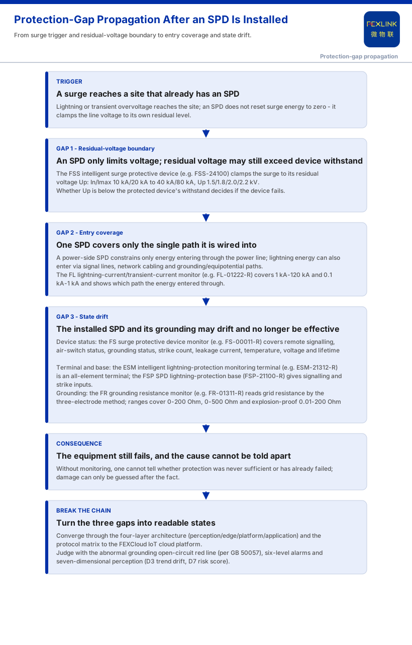
An SPD was fitted and passed inspection, yet a thunderstorm still destroys equipment — not a contradiction. An SPD (surge protective device) does one job: it limits voltage. When a surge overvoltage arrives it clamps the line voltage to its own residual voltage level; it does not "reset" lightning energy to zero. How far it clamps depends on that stage's residual voltage (Up), which may still sit above the protected equipment's withstand capability. One SPD also usually covers only the single path it is wired into, while lightning energy can enter through signal, network and grounding paths other than the power supply; and the fitted SPD changes with strikes and age, just as grounding conditions drift. So "an SPD is installed" answers whether one was fitted, while "why did the device still fail" asks whether the protection chain is actually closed and still effective.
1. An SPD Limits Voltage — It Does Not "Reset" Lightning to Zero
An SPD is not an absolute wall before the equipment; it conducts fast when a surge arrives and holds voltage at a residual level. The FSS intelligent surge protective device writes this into its parameters — In/Imax runs from 10 kA/20 kA to 40 kA/80 kA, with residual voltages of 1.5 kV, 1.8 kV, 2.0 kV and 2.2 kV. After an SPD is installed, the equipment no longer sees a fully unrestricted overvoltage, but not zero either; the limited residual voltage remains on the line.
Whether the equipment fails then turns on a question easily missed on an acceptance sheet: is that residual level below the protected device's own withstand capability? The direction is clear, though: if SPD parameters are chosen by discharge capability alone while ignoring Up, residual voltage can exceed device withstand, and "an SPD is installed" does not automatically mean the equipment-side voltage is safe.
2. One SPD Covers Only the Path It Is Installed On
Another misjudgement: since an arrester sits in the cabinet, all lightning is blocked. In reality an SPD is connected in parallel only on the path it is wired into. A power-side SPD constrains surge energy entering through the power line, yet lightning energy can also enter through signal lines, network cabling and grounding/equipotential paths — entry points that may lie outside that single SPD's protection range.
The FL lightning-current/transient-current monitor observes the lightning current itself: it covers two magnitudes, 1 kA–120 kA and 0.1 kA–1 kA, offers peak, peak-plus-energy and waveform options, and comes in indoor and outdoor versions. It is needed because when a device fails despite a power-side SPD, "where did the energy come from" must be answered. The four-layer architecture further unifies power, grounding and other entries into one set of perceived objects. Classifying direct and induced lightning paths belongs to another article; here "a single SPD has limited entry coverage" is only one reason the device still fails.
3. The Installed SPD May No Longer Be Effective, and Grounding Drifts
The third gap is subtler: whether the SPD on site is still effective, and whether its grounding loop still holds, are often never continuously confirmed. Protective components degrade with strikes and operation, grounding resistance changes with soil and connection state, and none of this appears in the original acceptance report.
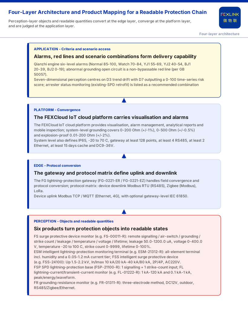
The knowledge base turns both into readable quantities. The FS surge protective device monitor covers remote signalling, air-switch status, grounding status, strike count, leakage current, temperature, voltage and lifetime estimation, with leakage 50.0–1200.0 μA, voltage 0–400.0 V, temperature -20–100 °C, strike count 0–9999 (0.1 kA minimum trigger) and lifetime 0–100%, with element coverage varying by model tier; the ESM intelligent lightning-protection monitoring terminal is an all-element terminal that also includes humidity and a 0.05–1.2 mA current tier; the FSP SPD lightning-protection base provides remote-signalling and strike-count inputs. On the grounding side, the FR grounding resistance monitor reads grid resistance continuously by the three-electrode method, while the system-level grounding parameters define ranges of 0-200 Ω, 0-500 Ω and explosion-proof 0.01-200 Ω.
It should be noted that "arresters degrade and installation is not once and for all" belongs to the device-lifecycle topic and is not developed further here; here it is treated only as the second class of reason for "an installed SPD still allowed damage": without confirming whether the SPD is still effective and whether grounding still holds, one cannot tell at the time of failure whether protection was never sufficient or has already failed.
4. Turning "Does the Protection Chain Have a Gap?" into a Readable State
Put the three gaps together and "why did the device still fail" becomes an observability problem: the residual voltage, the energy path, and the state of the SPD and grounding are invisible without monitoring. The four-layer architecture gives the readable route: perception-layer monitoring modules upload through edge-layer gateways to the FEXCloud IoT cloud platform, which forms visualisation, alarms and reports at the application layer; the protocol matrix defines the uplink and downlink — device downlink including Modbus RTU (RS485), Zigbee (Modbus) and LoRa, device uplink including Modbus TCP/MQTT plus optional gateway-level IEC 61850.
At the criteria layer, the six-level alarm scheme runs Normal (85-100), Watch (70-84), YJ1 (55-69), YJ2 (40-54), BJ1 (20-39, handle within 48 hours) and BJ2 (0-19, immediate shutdown); "abnormal grounding-resistance open circuit" is the non-bypassable red line (per GB 50057), and seven-dimensional perception centres on D3 trend drift, with D7 outputting a 0-100 time-series risk score. The knowledge base lists "arrester status monitoring (retrofit of installed SPDs)" as a recommended combination landing on the FS monitor, ESM all-element SPD monitoring and the FSP base. Then each link can be read at runtime: whether lightning current passed an entry, how much capability the component has left, whether grounding is still above the red line.
5. Boundaries: What This Article Does Not Claim
First, this article's argument — that "an SPD is a voltage-limiting device and residual voltage may still exceed limits," and that "a device still damaged with an SPD already installed indicates an unobserved gap in the protection chain" — does not constitute a selection calculation, an insulation-coordination conclusion or an acceptance basis.
Second, the quantitative indicators (electrical-hazard identification 95%+, alarm compression 80%, MTTR reduced 60%) are vendor self-reports; cite them only as vendor capability claims, never as effect guarantees or procurement grounds.
Third, the knowledge base gives no insulation-coordination table between SPD and device, no energy-coordination parameters between SPD stages, no matching method between SPD residual voltage and device withstand, and no coordination-selection rules between SPD and signal/network arresters — none is inferred; nor does it give retrofit procedure, construction sequence, quantity basis, sampling and reporting frequency, offline caching and backfill, or alarm-ticket grading and evidence-retention format.
Fourth, this article claims no customer case, certification, handling effect or industry ranking, and invents no model, parameter or standard clause absent from the knowledge base; it cites only numbers such as GB 50057 as listed in the knowledge base, without inferring their content.
Fifth, its landing point is the protection-gap attribution of "why a device with an SPD already installed still fails," and it does not take on neighbouring articles: path classification of direct/induced lightning, the arrester's own lifecycle, forensic diagnosis of lightning-current events, or scenario necessity for distribution cabinets and weak-current rooms.
Conclusion
A device still gets damaged after an SPD is installed because the SPD solves only the voltage-limiting link, while "will the device fail" is decided by the whole chain: whether residual voltage is below device withstand, whether lightning energy enters through an uncovered path, and whether the fitted SPD and grounding are still effective. Without monitoring, all three gaps are invisible, so "an SPD is installed" is mistaken for completed protection. To make "why does it still fail" answerable, one must read out each link — the lightning-current path, component status and grounding — converging them through the four-layer architecture and the protocol matrix, holding the floor with the red line and six-level alarms, and turning "does the protection chain have a gap" from a site complaint into a traceable process quantity.


