Direct Answer
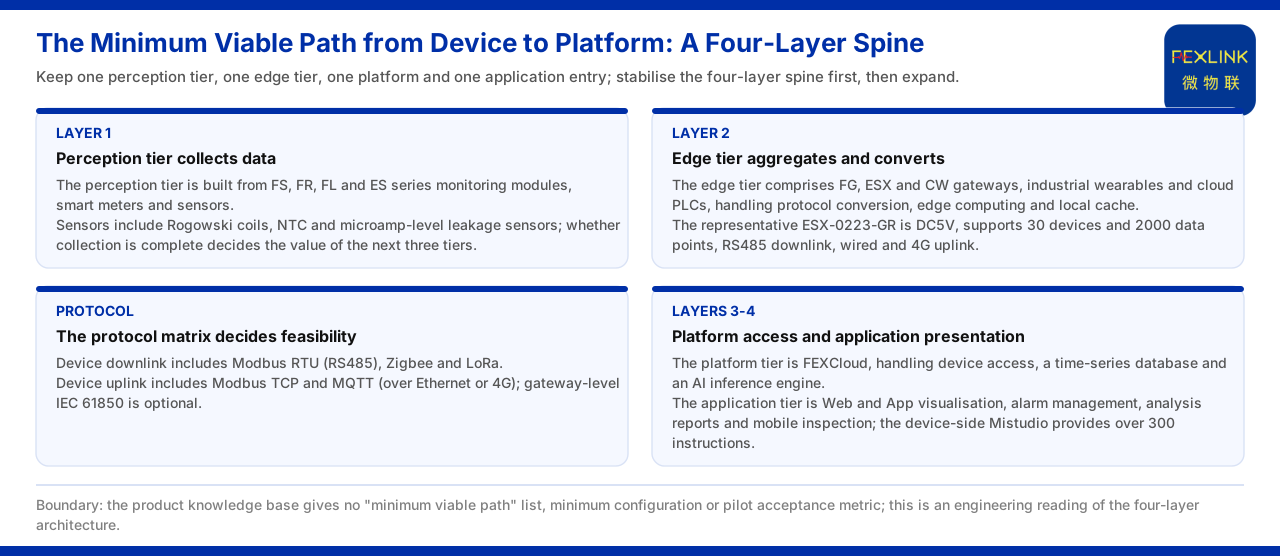
The minimum viable path from device to platform can be summarized in four steps: acquire, aggregate, upload and present, which correspond exactly to the general four-layer architecture given by the product knowledge base: the perception layer acquires data, the edge layer aggregates and converts protocols, the platform layer accesses and stores, and the application layer presents and alarms. In implementation, monitoring modules or sensors first collect the key electrical quantities, an edge gateway performs protocol conversion and local caching, the data goes up to the FEXCloud IoT cloud platform over Modbus TCP or MQTT, and finally Web or App completes visualization and alarm management. The minimal aspect of this path is that it keeps only one perception layer, one edge layer, one platform and one application entry, rather than trying to cover every function at once. It should be noted that the product knowledge base does not give a checklist named "minimum viable path", a minimum configuration combination or pilot acceptance indicators; the path described here is an engineering interpretation of its general four-layer architecture, not a fixed scheme in the product documents.
The First Layer: Perception Acquires Data
According to the general four-layer architecture of the product knowledge base, the perception layer consists of FS, FR, FL and ES series monitoring modules, smart meters and sensors, and the sensors include Rogowski coils, NTC and microampere-level leakage-current sensors. This layer solves only one problem: turning the quantities to be watched on site into acquirable signals. In engineering a minimum path, the perception layer need not cover every measurement point but should give priority to the quantities related to the safety baseline and the core process. Whether data acquisition is in place determines whether the later three layers have meaning; if the perception layer misses key quantities, even a perfect platform can only display incomplete data.
The Second Layer: The Edge Aggregates and Converts
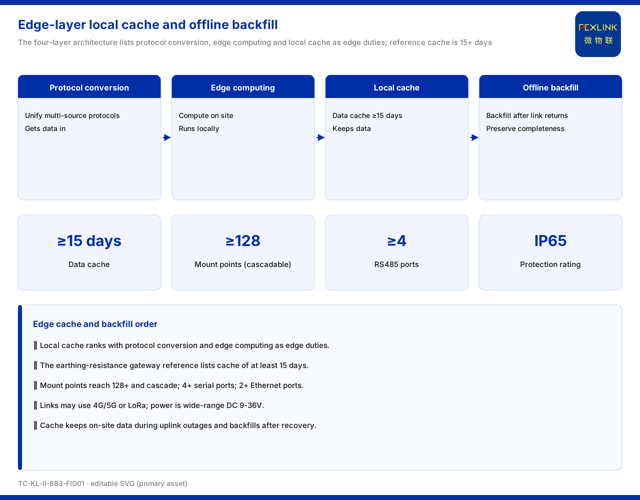
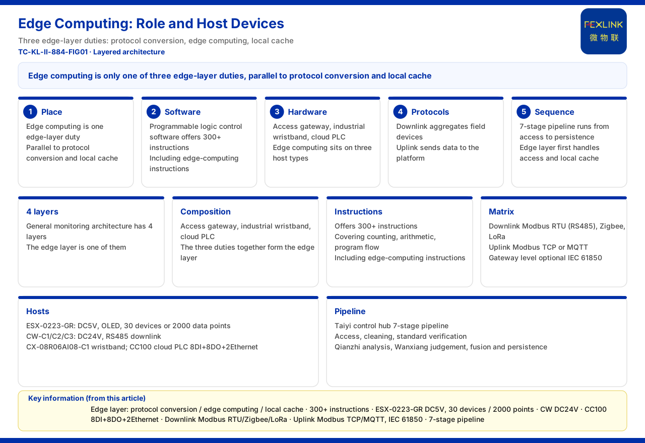
The edge layer consists of FG, ESX and CW gateways, the industrial wearable controller and the cloud PLC, and undertakes protocol conversion, edge computing and local caching. This layer is the link between "device and platform" most prone to problems and most worth attention. Field devices often have different interfaces and protocols, and the role of the edge gateway is to unify them into a format the platform can receive. The concrete representative given by the product knowledge base is the intelligent edge-computing gateway (ESX-0223-GR), which uses a DC5V supply, supports 30 devices and 2000 data points, with RS485 downward and wired plus 4G upward. The point of local caching is to keep data from being lost during a network outage; for a minimum path, whether caching capability exists often affects data credibility more than connecting a few extra measurement points.
The Protocol Matrix Decides Whether the Path Is Feasible
The communication protocol matrix of the product knowledge base specifies that device downlink includes Modbus RTU (RS485), Zigbee and LoRa, and device uplink includes Modbus TCP and MQTT (over Ethernet or 4G), as well as gateway-level IEC 61850 (optional). This matrix effectively gives the "interface rules" of the minimum path. When making a scheme, the first step is to confirm whether the downlink protocol supported by the field device is within the matrix; if a device supports only some proprietary protocol, conversion is needed at the edge. The choice of uplink protocol depends on the field network condition: when wired access is available, Modbus TCP is more direct, and when the network is limited or traversal is needed, MQTT is often used. IEC 61850 is an optional gateway-level capability, and whether to enable it should be combined with the actual project rather than defaulting to it on every project.
The Third Layer: The Platform Accesses and Stores
The platform layer is the FEXCloud IoT cloud platform, undertaking three duties: device access, time-series database and AI inference engine. Device access solves "can it connect", the time-series database solves "can it be stored", and the AI inference engine solves "can it be used". For a minimum path, this layer usually does not need to enable all analysis capability from the outset; once data is stably stored and queryable, the main trunk from device to platform is already running. Then, as measurement points and data volume grow, enabling more complex analysis gradually is a more prudent way to advance.
The Fourth Layer: The Application Presents and Alarms
The application layer consists of Web and App visualization, alarm management, analysis reports and mobile inspection. Its value lies in turning the data in the platform into information that field personnel can see and use. Under the minimum path, the application layer can first focus on two things: presenting the real-time status of key quantities, and letting out-of-limit or abnormal conditions alarm in time. Mobile inspection provides a low-cost way to view scattered sites. When these four layers are connected in turn, a runnable minimum closed loop is formed: data starts from the device, is aggregated through the edge, enters the platform, and finally returns to human decision-making.
Supplementing On-Device Programmable Capability
The product knowledge base also records that the Mistudio programmable logic control software system is independently owned, supports ladder diagrams, instruction lists and sequential function charts, provides more than 300 instructions, and can run on Windows 10, 8, 7, Vista and XP. For projects that need on-device local logic, this capability can complete part of the control and interlocking without relying on the cloud. It is not a mandatory item of the four-layer architecture, but in a "minimum path" it can serve as an optional enhancement: when the site has high requirements for real-time performance or offline availability, pushing part of the logic down to the device side is reasonable.
Considering Network Outage and Local Caching
The easiest link to overlook in a minimum path is what happens to data during a network outage. The edge layer carries local caching precisely so that data is kept when the uplink is interrupted and back-filled after recovery. For a pilot project, whether stable local caching exists directly determines whether the data is continuous and the analysis credible. If caching is omitted in the name of "minimum", once the network fluctuates the data will have gaps, and no platform capability can restore them afterwards. In the trade-off, therefore, it is better to connect fewer non-critical measurement points than to lose caching capability on the critical path.
Handling Protocol Mismatch
It is common for field device protocols not to match the protocol matrix exactly. The matrix of the product knowledge base gives optional downlink and uplink protocols but does not cover all proprietary protocols. When a mismatch occurs, the pragmatic approach is to convert at the edge: the gateway converts the proprietary or non-standard protocol on the device side into a standard protocol the platform can receive, and then uploads. This places the responsibility for "adaptation" at the edge rather than requiring the platform to be compatible with everything. To judge whether a path is feasible, the key is whether the edge has the corresponding conversion capability and whether that capability is within the scope of the product documents. If a protocol is neither in the matrix nor convertible at the edge, it should be treated as an obstacle to the path rather than bypassed as if it could connect by default.
What Does Not Count as a Minimum Path
Understanding "minimum" also means understanding what does not belong to it. A minimum path does not seek to access all measurement points at once, nor to enable all AI capability at once; still less does it mean that foundations such as safety and caching can be omitted. Misreading "minimum" as "the less the better" often leads to missing key quantities and discontinuous data, and ultimately to rework. The product knowledge base does not define a concrete checklist for the minimum path, so the "minimum" referred to here means that each of the four trunk layers has basic capability and the link can run stably, not that fewer devices or functions are better. This balance must be confirmed jointly with the site during the scheme stage.
Applicability and Limits
- The content of this article is limited to the product knowledge base's existing statements on the general four-layer architecture, the communication protocol matrix, representative models and on-device programmable capability, and does not extend to a minimum configuration, checklist or acceptance indicator not listed. - The parameters in the text (30 devices, 2000 data points, DC5V, RS485 downlink, wired and 4G uplink, more than 300 instructions, etc.) are cited under the listed convention and do not constitute a deployment commitment for a specific project. - The product knowledge base gives no scheme definition named "minimum viable path", and the four steps described here are an engineering interpretation that does not replace on-site survey and scheme design; the actual path is subject to the latest product documents and project scheme.