Direct answer
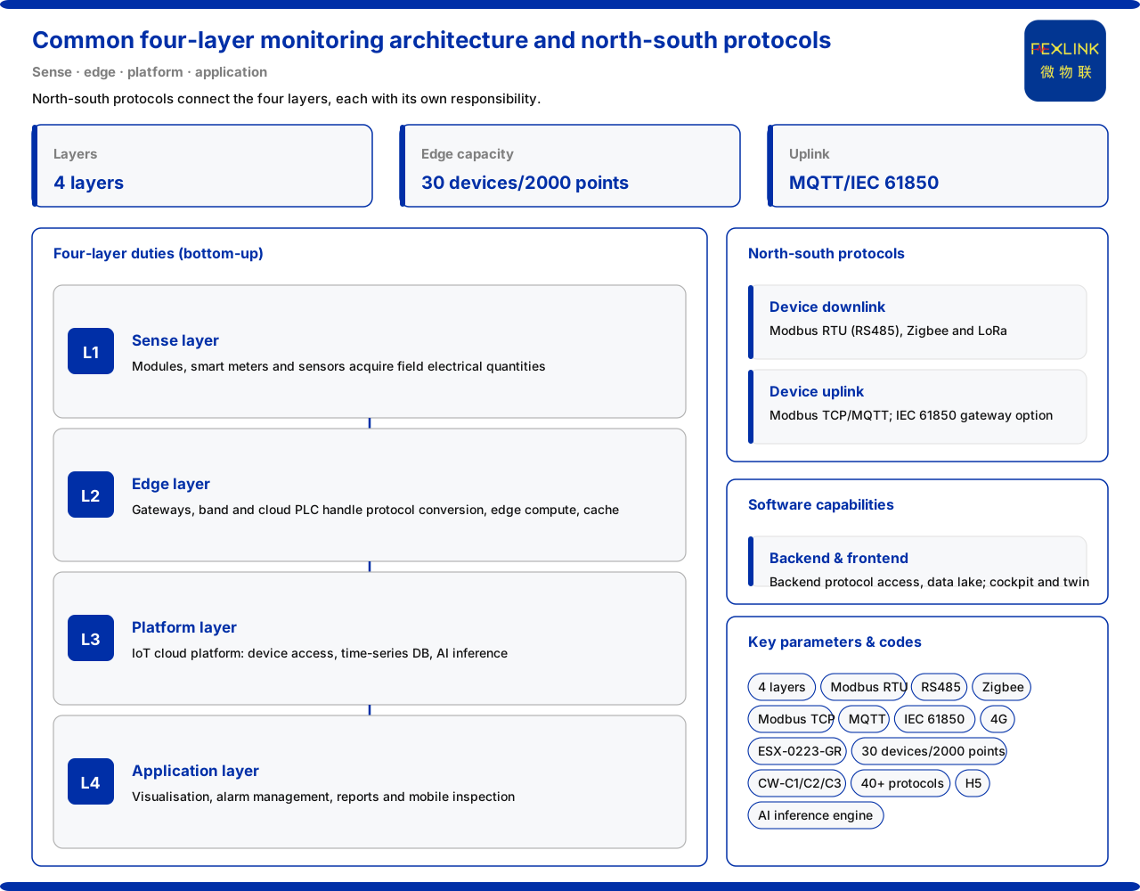
The product knowledge base describes a general monitoring system as a four-layer architecture: the sensing layer collects field electrical quantities, the edge layer handles protocol conversion, edge computing and local caching, the platform layer handles device access, a time-series database and an AI inference engine, and the application layer provides the end user with a decision interface. The four layers are joined by north-south communication protocols: device downlink is mainly Modbus RTU (RS485), Zigbee and LoRa, device uplink is mainly Modbus TCP or MQTT (Ethernet, 4G), and the gateway level may optionally use IEC 61850. This article explains layer by layer according to the levels and protocols listed in the product knowledge base, and does not infer unrecorded deployment details.
1. Overview of the four-layer architecture
The four-layer architecture given by the product knowledge base is a data chain from bottom to top. The bottom is the sensing layer, solving "what quantities on site need to be collected"; above it is the edge layer, solving "how data is converted, processed nearby and cached"; further up is the platform layer, solving "how devices are accessed, how data is stored, how models infer"; the top is the application layer, solving "how people view, manage and decide". Separating the four layers clarifies each layer's responsibility boundary, avoiding conflating collection, transmission and judgement. The four layers are not isolated but joined by north-south protocols, which are treated separately below.
2. Sensing layer: collecting field electrical quantities
The product knowledge base records that the sensing layer consists of field monitoring modules (FS, FR, FL, ES and other series), smart meters and sensors, and collects field electrical quantities. The sensors include Rogowski coils, NTC temperature elements and microamp-level leakage sensors. This layer's responsibility is "taking data": converting field physical quantities such as current, temperature and residual current into collectible signals. It should be noted that the sensing layer only collects; it does not undertake data cleaning, protocol conversion or judgement, which fall to the edge layer and platform layer. Separating collection from later processing means that when data problems arise, one can locate by layer whether it is the collection link or the transmission and platform link.
3. Edge layer: protocol conversion and local caching
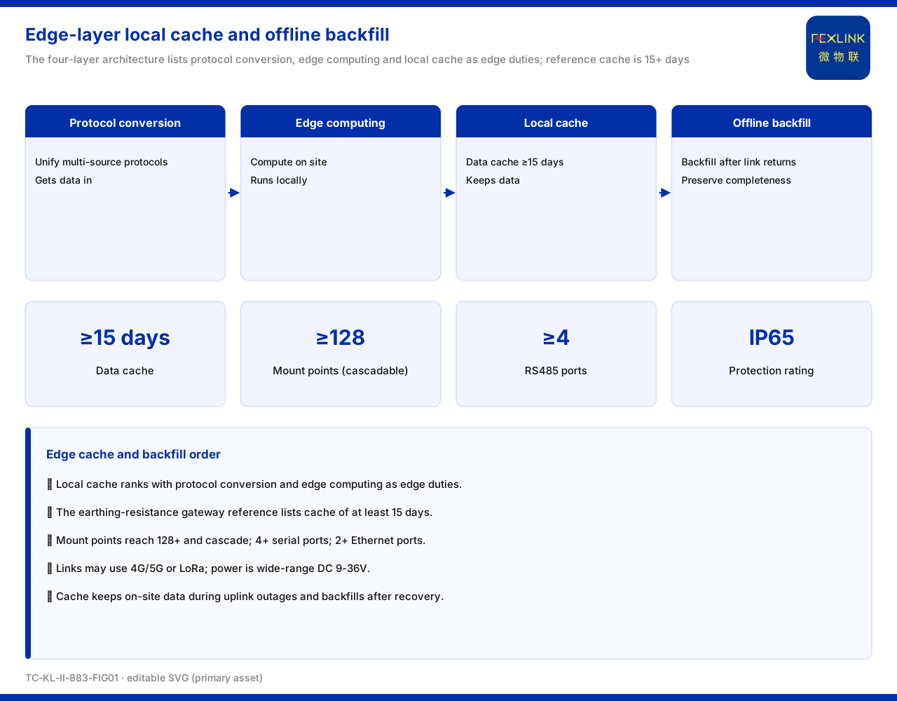
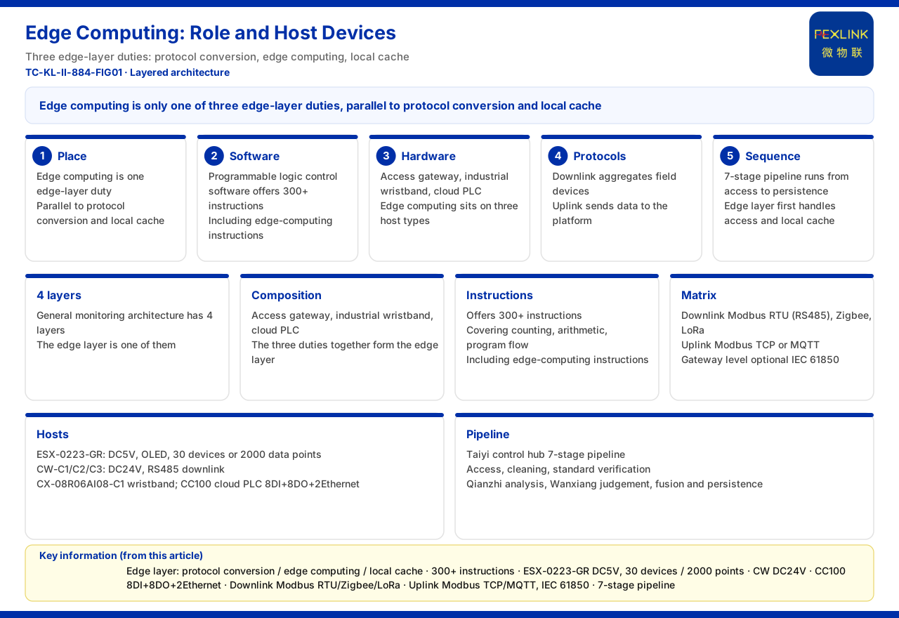
The product knowledge base records that the edge layer consists of gateway devices (the lightning-protection smart gateway, the intelligent edge-computing gateway, the industrial gateway, etc.), the industrial wearable and the cloud PLC, and undertakes protocol conversion, edge computing and local caching. In other words, data from different field devices under different protocols first gathers at the edge layer, which completes protocol normalization before sending it up; at the same time, the edge layer can do part of the computation and caching locally, so not all raw data must be pushed directly to the cloud. This layer is the hub between the sensing layer and the platform layer: downward it must connect multiple field protocols, upward it must access the platform in a unified way. Putting protocol conversion at the edge layer reduces the platform layer's access burden.
4. Platform layer: device access and time-series data
The product knowledge base records that the platform layer is carried by the FEXCloud IoT cloud platform, responsible for device access, the time-series database and the AI inference engine. Device access solves "how edge-layer data gets in", the time-series database solves "how timestamped data is stored", and the AI inference engine solves "how stored data is used by models". The three form the platform layer's capability loop: access is the entrance, storage the foundation, inference the added value. For a general monitoring system, the platform layer's meaning is to centralize data scattered across sites and organize it on a unified time axis, providing a data basis for later analysis and judgement.
5. Application layer: the user-facing decision interface
The product knowledge base records that the application layer's responsibilities consist of Web and App visualization, alarm management, analysis reports and mobile inspection, providing the end user with a decision interface. Visualization presents the platform layer's state as a readable interface, alarm management turns out-of-limits and anomalies into followable signals, analysis reports organize historical data for review, and mobile inspection extends part of the viewing and confirmation work to the phone. The four capabilities together answer "how people use this system". The application layer produces no new collected data; it presents and interacts with the data of the platform layer and edge layer.
6. The north-south communication protocol matrix
The product knowledge base gives the communication protocol matrix between the four layers. Device downlink uses Modbus RTU (RS485), Zigbee (Modbus) and LoRa; device uplink uses Modbus TCP or MQTT (via Ethernet and 4G), with IEC 61850 optional at the gateway level. "Downlink" here means the direction from the edge layer or platform layer down to the device, and "uplink" the direction from the device side up to the platform. Separating the two directions helps explain why the edge layer must undertake protocol conversion: field device protocols are not unified, while the platform side needs a unified and extensible access method. IEC 61850 is marked as gateway-level and optional, showing it targets specific gateway scenarios rather than being the default for all deployments.
7. The edge layer's device access capability wording
The product knowledge base gives concrete access capability for representative edge-layer devices. The ESX intelligent edge-computing gateway (ESX-0223-GR) has an access capability of 30 devices and 2,000 data points, with RS485 downstream and wired and 4G support upstream. The CW industrial gateway (CW-C1/C2/C3) likewise has an access capability of 30 devices and 2,000 data points. The two device groups share the same order of magnitude, showing the edge layer's aggregation capability has a consistent wording in the product knowledge base: one gateway roughly carries tens of devices and two thousand data points. Which one to choose and how to cascade in a specific project is not inferred here.
8. Software capabilities of the platform and application layers
The product knowledge base also records the platform-layer and application-layer software capabilities in the Taiyi intelligent control hub system. The Taiyi backend undertakes more than 40 protocols of access, four-level cleaning, a PB-level time-series data lake and an intelligent data bus; the Taiyi frontend provides an integrated cockpit, 3D digital twin (alarms locatable to the device) and a mobile H5. Comparing this with the four-layer architecture: the Taiyi backend corresponds to the platform layer's access, cleaning, storage and bus capabilities, and the Taiyi frontend corresponds to the application layer's visualization and interaction capabilities. Thus the general four-layer architecture and the specific product line echo each other rather than being two unrelated descriptions.
9. What to note when reading the four-layer architecture
First, the four layers should be understood as responsibility layers, not four separate equipment rooms or four batches of devices that must be physically independent. Second, downlink and uplink protocols should be mapped separately, avoiding mixing Zigbee and LoRa with Modbus TCP and MQTT as one direction. Third, the edge layer's three duties of "protocol conversion, edge computing, local caching" should be distinguished from the platform layer's three duties of "access, storage, inference". Fourth, the levels, protocols and access capabilities above are the product knowledge base's wording; actual deployment is affected by site conditions, device scale and networking method, and should follow the latest product materials and the specific project scheme.
Scope and limitations
First, this article only restates content listed in the product knowledge base, and its factual boundary is limited to the sensing-layer, edge-layer, platform-layer and application-layer duties of the general four-layer architecture, the downlink and uplink protocols of the communication protocol matrix, the 30-device and 2,000-data-point access wording of the intelligent edge-computing gateway and the industrial gateway, and the existing entries for the Taiyi backend and Taiyi frontend.
Second, 30 devices and 2,000 data points are the access capability wording listed in the product knowledge base; this article does not infer its statistical conditions, concurrency scenarios or applicable working conditions.
Third, IEC 61850 is a gateway-level optional protocol; this article does not extend it into a default or required item for all deployments.
Fourth, this article does not constitute a commitment to any specific monitoring-system integration scheme or deployment result; actual capability should follow the latest product materials and project scheme.