How the CX industrial wearable differs from an ordinary data acquisition terminal
Direct answer
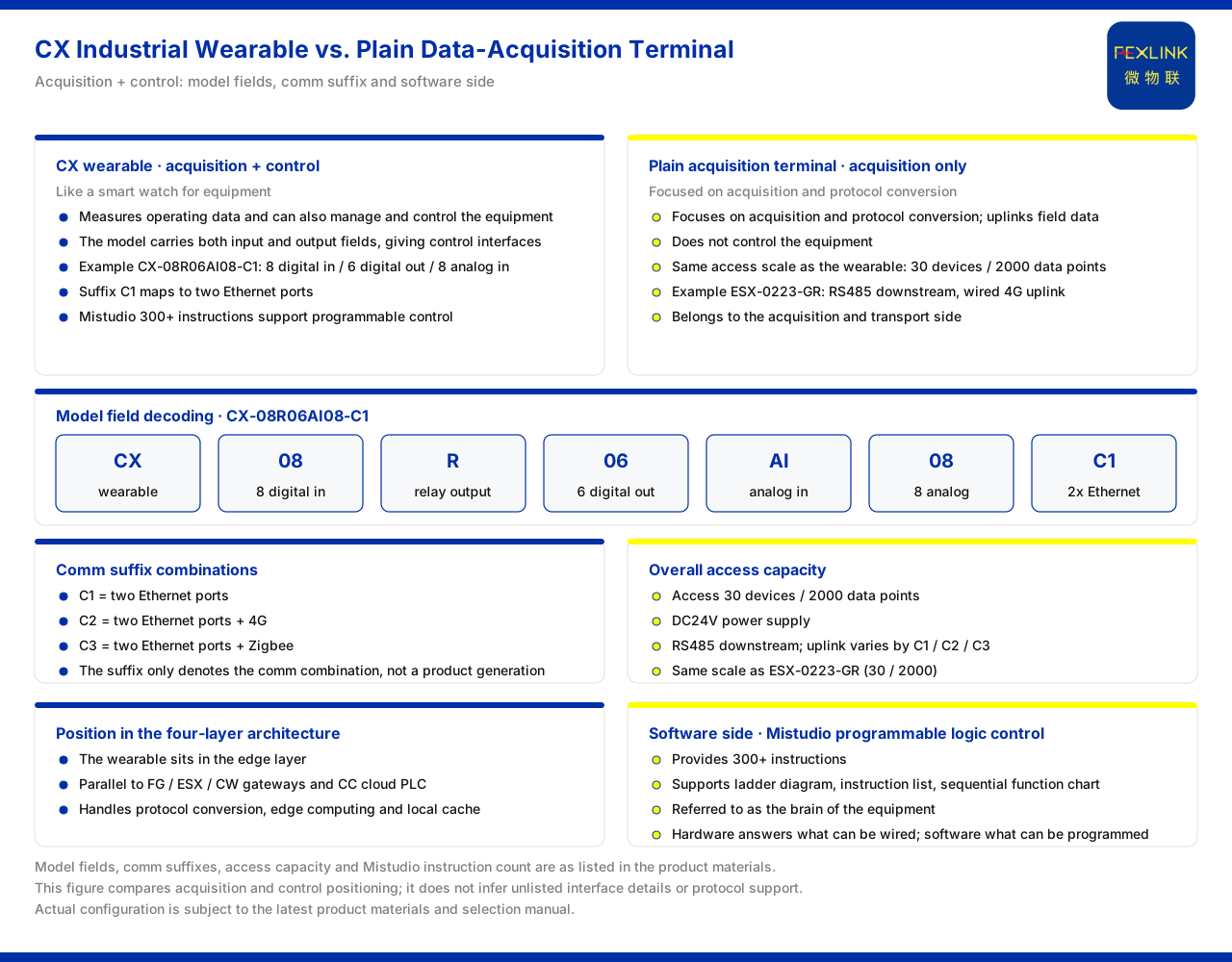
The difference between the two begins with positioning. The product knowledge base positions the CX industrial wearable controller (programmable device wearable, e.g. CX-08R06AI08-C1) as being like putting a "smart watch" on a device: while collecting device operating data, it can also manage and control the device, and is called the "device brain"; an ordinary data acquisition terminal is responsible only for acquisition and does not undertake control. This positioning difference is also reflected in the model fields and the supporting software. Taking the example model CX-08R06AI08-C1, 08 indicates the number of digital input points, R indicates relay-type output, 06 indicates the number of digital output points, AI indicates analog input, 08 indicates the number of analog points, and the communication suffix C1 corresponds to 2 Ethernet ports. The supporting Mistudio programmable logic control software system (compiler) provides more than 300 instructions and supports such languages as ladder diagram, instruction list and sequential function chart, and is called the brain of the device. On connection capability, the industrial wearable series supports 30 devices and 2000 data points, is supplied at DC24V, and uses RS485 for downstream communication. In the four-layer architecture of the monitoring system it sits in the edge layer, alongside the gateway and the cloud PLC.
1. Positioning first: acquisition, or acquisition plus control
The product knowledge base positions the industrial wearable as being like putting a "smart watch" on a device: while collecting device operating data, it can manage and control the device, and calls it the "device brain". This statement contains two actions: acquisition and control. The function of an ordinary data acquisition terminal is concentrated on acquisition and protocol conversion, taking field data out and transmitting it upward; it does not undertake control of the device. The industrial wearable adds management and control capability on this basis. It is precisely this positioning that distinguishes it from a pure acquisition terminal and determines its role in an intelligent-upgrade project: when a project only needs to read data, a pure acquisition terminal suffices; when a project needs to issue control logic to the device while reading data, the industrial wearable has the corresponding capability foundation.
2. How the model fields embody the dual capability
The model of the industrial wearable is not a random number but a configuration statement that can be verified field by field. The example model given by the product knowledge base is CX-08R06AI08-C1. According to the field description, the leading CX indicates that this is an industrial wearable; the following 08 indicates the number of digital input points; the next R indicates relay-type output; the 06 after that indicates the number of digital output points; the subsequent AI indicates analog input, and the 08 immediately following it is the number of analog points. Digital input is used to collect switching-quantity signals, digital output and relay-type output form the interface for the device to execute actions, and analog input is used to collect continuous-quantity signals. Including both input and output in the model fields itself shows that this device has interface configuration on both the acquisition and the control sides, and is not merely a one-way reader.
3. Communication suffix and connection capability
The product knowledge base gives three communication suffixes: C1 corresponds to 2 Ethernet ports, C2 corresponds to 2 Ethernet ports plus 4G, and C3 corresponds to 2 Ethernet ports plus Zigbee. The example model ends in C1, so its communication method is 2 Ethernet ports. The suffix indicates only the combination of communication methods; during selection one simply matches it to whether the site needs 4G or Zigbee, and it should not be read as a product generation. On whole-unit capability, the product knowledge base records that the industrial wearable series supports 30 devices and 2000 data points, is supplied at DC24V, uses RS485 for downstream communication, and distinguishes its upstream communication by the combinations of C1, C2 and C3 in the same way. The supply method, the number of connectable devices and the number of data points are whole-unit parameters outside the model fields; they cannot be read from the model alone and must be confirmed separately during selection.
4. Comparison with a pure acquisition gateway
To understand the positioning of the industrial wearable, it can be compared with a pure acquisition or protocol-conversion device. The product knowledge base records that the ESX intelligent edge-computing gateway (e.g. ESX-0223-GR) has the same connection capability of 30 devices and 2000 data points, uses RS485 downstream and wired 4G upstream. In terms of connection scale, the industrial wearable and this class of gateway are of the same order, both oriented to a relatively large number of devices and data points. The difference lies in positioning: the edge-computing gateway mainly undertakes protocol conversion and data uplink and belongs to the acquisition and transmission side, while the industrial wearable provides control capability in addition to acquisition and belongs to the programmable control side. Comparing two devices of similar connection capability shows that "whether it can control" is the key that distinguishes them, not the number of connections itself.
5. The software side: where the programmable capability comes from
Control capability needs software-side support. The product knowledge base records that the Mistudio programmable logic control software system (compiler) provides more than 300 instructions, supports such languages as ladder diagram, instruction list and sequential function chart, and is called the brain of the device. This description shows that the "device brain" positioning of the industrial wearable is not achieved by hardware interfaces alone but also needs programmable logic as its software foundation. For an upgrade project, this means that when assessing the industrial wearable, in addition to checking the I/O point counts and communication method, one should also assess whether the instructions and languages of the programmable software meet the needs of the control logic. The hardware interfaces answer what can be connected, while the software capability answers what can be programmed; together they determine the boundary of the control function.
6. System placement and selection
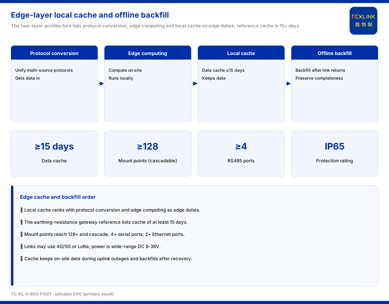
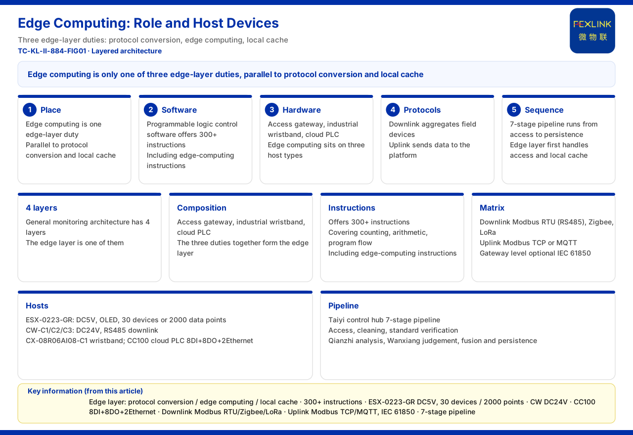
In the general four-layer architecture of the monitoring system, the industrial wearable sits in the edge layer, alongside the gateway and the cloud PLC, and undertakes such edge-side duties as protocol conversion, edge computing and local caching. In the typical application scenarios and selection comparison, the product combination corresponding to industrial equipment intelligent upgrading is the industrial wearable or the cloud PLC with expansion modules, together with Mistudio. That is, when the upgrade goal is to give equipment acquisition-plus-control capability, the selection points to this combination. The industrial wearable suits occasions where interface needs and programmable needs are relatively concentrated, while the cloud PLC with expansion modules suits occasions needing more expansion; the specific selection should be confirmed item by item in conjunction with the on-site I/O needs and control logic, and this article provides no configuration conclusion.
Scope and limitations
- This article is limited to what the product knowledge base lists: the "device brain" positioning of the industrial wearable, the meaning of each field of the example model CX-08R06AI08-C1, and the C1, C2 and C3 communication-suffix combinations. - The 30 devices, 2000 data points, DC24V supply and RS485 downstream of the industrial wearable series, and the same-order connection capability of the intelligent edge-computing gateway, are restated as listed by the product knowledge base. - The more than 300 instructions of Mistudio and such languages as ladder diagram, instruction list and sequential function chart are limited to the product knowledge base; this article does not infer their specific instruction content or programming details. - The device listing of the edge layer in the four-layer architecture and the combination in the selection comparison are given as listed by the product knowledge base; this article provides no specific engineering configuration or control-scheme conclusion. - This article does not infer unlisted interface details, output forms or protocol-support scope; actual configuration is subject to the latest product materials and selection manual.