Direct answer
The model code of the CX industrial wearable controller (programmable device wearable, e.g. CX-08R06AI08-C1) is not a random number but a hardware configuration statement that can be verified field by field. According to the product knowledge base description of the CX model fields, the leading CX indicates that this is an industrial wearable; the following 08 indicates the number of digital input points; the next R indicates relay-type output, while T would indicate transistor-type output; the 06 after that indicates the number of digital output points; the subsequent AI indicates analog input, and the 08 immediately following AI is the number of analog points; the trailing C1 indicates 2 Ethernet ports. In other words, the model itself tells you the digital input, digital output and analog input configuration of this industrial wearable, as well as its communication combination. Memorise the field order and you can avoid mismatching I/O point counts during selection, ordering and drawing annotation.
Field order and how to read the model at a glance
The CX model example given by the product knowledge base is CX-08R06AI08-C1, together with an explanation of each field. According to that field description, a complete model carries seven kinds of information from front to back: the product-family prefix, the digital input point count, the output-type code, the digital output point count, the analog input identifier, the analog point count, and the communication suffix. This order is fixed, so the model can be read in segments without first looking up a table and guessing.
The value of understanding the fixed order is that every digit or letter in the model is not decoration but corresponds to a concrete interface capability. During selection, reading the model segment by segment confirms how many digital inputs the device needs, what form of output is required, whether analog input is present, how many analog points there are, and which communication method is used. This is also the precondition for treating the model as a verifiable basis for ordering.
Field-by-field breakdown
The first segment is the product-family prefix CX. The knowledge base makes clear that in the CX industrial wearable model example, the prefix CX indicates an industrial wearable. The prefix therefore carries the function of identifying the product category, placing the model in the industrial wearable family.
The second segment is the digital input point count. In the example model, the 08 after CX indicates the number of digital input points, namely 8 points. This field directly determines how many digital input signals the device can accept, and it is the first item confirmed in an I/O configuration.
The third segment is the output-type code. The knowledge base states that the output-type code R is relay-type output and T is transistor-type. The example model uses R, so its output form is relay-type; if the code in the same position were T, the output form would be transistor-type. This position determines the implementation form of the output circuit and should be checked against the load type during selection.
The fourth segment is the digital output point count. In the example model, the 06 after the output-type code indicates the number of digital output points, namely 6 points. It belongs to a separate segment from the preceding digital input point count and must not be confused with it: the earlier 08 refers to inputs, while this 06 refers to outputs.
The fifth segment is the analog input identifier together with its point count. The knowledge base states that AI indicates analog input, and the digit 08 immediately following it is the analog point count of that part, namely 8 points. Note in particular that AI and the digit after it are bound together: AI is the identifier and only the digit immediately following it is the point count. The digit after AI must not be mistaken for a digital-side configuration.
The sixth segment is the communication suffix. The knowledge base gives three communication combinations: C1 corresponds to 2 Ethernet ports; C2 corresponds to 2 Ethernet ports plus 4G; C3 corresponds to 2 Ethernet ports plus Zigbee. The example model ends in C1, so its communication method is 2 Ethernet ports. The suffix indicates only the combination of communication methods, and during selection you simply match it to whether the site needs 4G or Zigbee.
Reading a complete model
Joining the seven segments above, CX-08R06AI08-C1 reads in full as: this is a CX industrial wearable; digital input 8 points; output type relay; digital output 6 points; analog input 8 points; communication 2 Ethernet ports.
Three verification conclusions follow. First, the digital input point count comes from the first digit after CX, here 08, that is 8 points. Second, the digital output point count comes from the digit after the output-type code, here 06, that is 6 points, and must not be confused with the input 08. Third, the analog point count comes from the digit after AI, here also 08, that is 8 points. Once these three numbers are each placed correctly, the meaning of the model is entirely clear.
How the model maps to the unit parameters
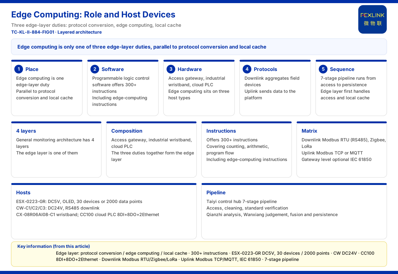
The model describes the I/O and communication configuration, while some unit parameters must be confirmed separately. In the knowledge base parameter table, the CX-08R06AI08 series is supplied at DC24V, with a connection capability of 8 digital channels plus 8 analog channels, can connect 30 devices and 2000 data points, and uses RS485 for downstream communication.
Comparing these parameters with the model shows that the 8 digital input points and 8 analog points in the model echo the connection statement of "8 digital channels plus 8 analog channels" in the parameter table, so the two can be checked against each other. On the other hand, the supply voltage, the number of connectable devices, the number of connectable data points, and the RS485 communication with subordinate devices are unit parameters outside the model fields; reading the model alone cannot reveal them, and they must be confirmed separately during selection. In other words, the model answers "what the interface configuration of this device looks like", while the parameter table answers "what its upstream/downstream capability and supply conditions are"; only together do they form a complete selection basis.
Common misreadings
The first is misreading the output-type code. The letter R in the example indicates relay-type output and T indicates transistor-type output; these two letters describe the output type and should not be mixed with other meanings.
The second is reversing the positions of the two numbers. The 08 after CX is the digital input point count and the 06 after the output-type code is the digital output point count; once the order is reversed, the input and output point counts are swapped.
The third is ignoring the binding between AI and the digit after it. AI indicates analog input and only the following 08 is the analog point count; treating the digit after AI as a digital configuration will misjudge the device's analog capability.
The fourth is treating the communication suffix as a product version number. The suffixes C1, C2 and C3 correspond respectively to the communication combinations listed by the knowledge base; they express a communication method, not a product generation.
Scope and limitations
- This article is limited to the existing statement of the product knowledge base on the CX industrial wearable model field rules, and is used to explain the meaning and reading of each field; it does not extend to interface details or other fields not listed by the knowledge base. - The example in the text follows CX-08R06AI08-C1; the suffixes C1, C2 and C3 correspond only to the communication combinations listed by the knowledge base and carry no other meaning. - The DC24V supply, the connection capability of 8 digital channels plus 8 analog channels, the 30 devices, the 2000 data points and the RS485 downstream communication are all in line with the knowledge base parameter table and do not constitute a commitment regarding selection results for any specific project. - The output type is explained only according to the two codes listed by the knowledge base, relay-type and transistor-type; this article does not extrapolate other output forms. - The actual configuration corresponding to the model fields is subject to the latest product materials and selection manual.