What the CW Industrial Gateway Suffixes C1, C2 and C3 Stand For
Direct answer
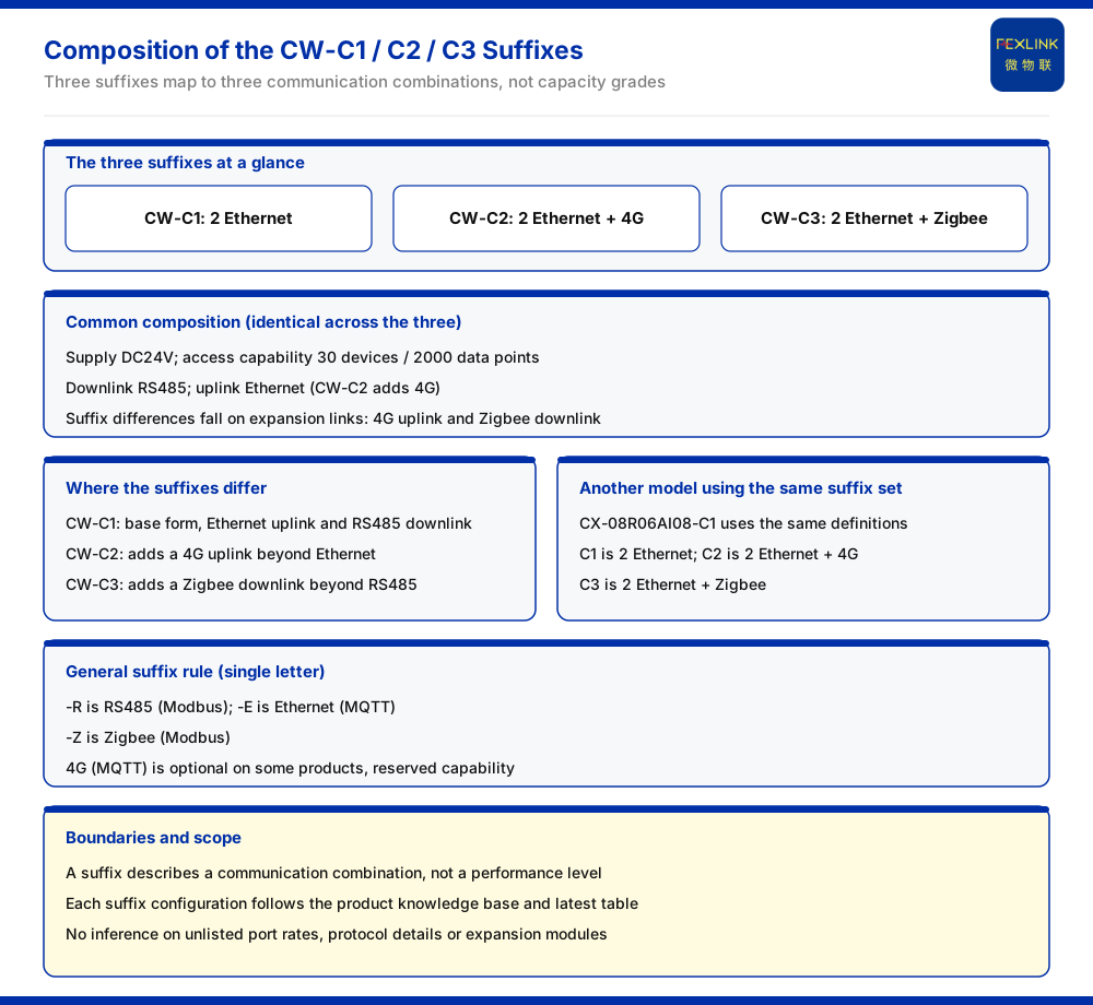
The three suffixes of the CW industrial gateway (e.g. CW-C1) each correspond to one communication configuration: the C1 suffix denotes 2 Ethernet ports; the C2 suffix denotes 2 Ethernet ports plus 4G; the C3 suffix denotes 2 Ethernet ports plus Zigbee. The three are identical in power supply, access capability, and downlink: all use DC24V, support 30 devices and 2000 data points, and provide RS485 as the downlink. The differences are concentrated in the expanded communication and the uplink: the C2 form adds 4G on the uplink beyond Ethernet, while the C3 form adds Zigbee on the downlink beyond RS485. In other words, the suffix is read as a communication combination, not as a capacity grade.
1. The three suffixes of the CW family
The CW industrial gateway models recorded in the product knowledge base are CW-C1, CW-C2, and CW-C3, with the suffix definitions in order: C1 is 2 Ethernet; C2 is 2 Ethernet plus 4G; and C3 is 2 Ethernet plus Zigbee. The parameters of the three are listed in the same parameter table as the intelligent edge-computing gateway, which shows that the CW family and the ESX series share the organization of one parameter table.
2. Parameter comparison of the three models
According to the parameter table, the C1 form is DC24V, with an access capability of 30 devices and 2000 data points, an RS485 downlink, and an Ethernet uplink. The C2 form is DC24V, with the same access capability of 30 devices and 2000 data points, an RS485 downlink, and an Ethernet plus 4G uplink. The C3 form is DC24V, with the same access capability of 30 devices and 2000 data points, an RS485 plus Zigbee downlink, and an Ethernet uplink. It can be seen that the power supply, access capability, and RS485 downlink of the three are the same, and the difference falls in two places: the 4G uplink and the Zigbee downlink.
| Model | Power supply | Access capability | Downlink | Uplink | |:--|:--|:--|:--|:--| | CW-C1 | DC24V | 30 devices and 2000 data points | RS485 | Ethernet | | CW-C2 | DC24V | 30 devices and 2000 data points | RS485 | Ethernet plus 4G | | CW-C3 | DC24V | 30 devices and 2000 data points | RS485 plus Zigbee | Ethernet |
3. The logic of the suffixes: read the communication combination
Set side by side, the suffix marks a communication combination rather than a performance level or a capacity size. C1 is the base configuration: Ethernet uplink and RS485 downlink. C2 adds 4G on top of the base configuration, for wireless fill-in or redundancy on the uplink; that is, it keeps one more uplink path besides wired Ethernet. C3 adds Zigbee on top of the base configuration, for small wireless networking on the downlink; that is, it connects one more class of wireless slave device besides RS485.
Once this layer of logic is understood, selection can be worked backward from the requirement. First, confirm whether the downlink needs Zigbee in addition to RS485: where the site has a Zigbee networking requirement, the C3 form should be considered; where it does not, the RS485 downlink of the C1 and C2 forms is already sufficient. Second, confirm whether the uplink needs 4G: where the site has no stable wired network, or where wireless redundancy is wanted beyond Ethernet, the C2 form should be considered; where the site has stable wired Ethernet, the C1 form is enough. Third, return to power supply and access capability for verification: all three are DC24V with an access capability of 30 devices and 2000 data points, so these two items do not distinguish the three and do not need to be compared again beyond the suffix.
4. The same suffix set across other models
The communication suffix is not unique to the CW family. The model example of the CX industrial wearable controller (programmable device wearable, e.g. CX-08R06AI08-C1) uses the same definition: C1 is 2 Ethernet, C2 is 2 Ethernet plus 4G, and C3 is 2 Ethernet plus Zigbee. That is, remembering the communication meaning of C1, C2, and C3 allows the suffixes of both the CW and the CX product classes to be read at once.
5. Correspondence with the general suffixes
In the more general model-naming rule, the communication suffixes also include: -R for RS485 (Modbus), -E for Ethernet (MQTT), and -Z for Zigbee (Modbus), with 4G (MQTT) noted as optional on some products and belonging to reserved capability. The C1, C2, and C3 used by the CW family are a grouped notation oriented to a gateway series, and belong to a different level of labeling from the single-letter suffixes above: a single-letter suffix describes the communication method or protocol of one link, while a grouped suffix describes the uplink and downlink combination of one gateway. Understanding this allows a model written either way to be judged as describing a protocol or a grouped communication configuration, and prevents the meaning of the two notations from being applied to one another. It should be noted that the specific configuration corresponding to each suffix is subject to what the product knowledge base and the latest parameter table list; this article only restates the listed horizons.
Scope and limitations
This article answers only "what the CW-C1, C2, and C3 suffixes stand for," and its content is limited to the suffix definitions, the parameters of the three models, the model example using the same suffix set, and the general suffix rule already recorded in the product knowledge base.
This article does not infer unlisted Ethernet port rates, protocol details, or expansion modules, nor does it draw a conclusion about network reachability at any site.
The suffix describes only a communication combination and does not represent a performance level; practical selection must be confirmed item by item in conjunction with on-site network conditions, access capability, and the latest product documentation.