Direct answer
After a reactive-power compensation device is switched in, the power factor should improve, but on site the phenomenon of "worse after compensation" sometimes appears: after compensation is switched in, current distortion worsens, voltage fluctuates or equipment behaves abnormally. Such problems are usually not a failure of the compensation device itself but a resonance formed between harmonics and the compensation capacitor. The judgement clue given by the product material is: first use an association rule to identify the combination of "high harmonics and reactive-power compensation being switched in occurring together", then use the power-quality monitor to acquire harmonic and power-factor data, and finally let the reactive-power compensation optimisation model of the Tianyan engine give a direction. This article explains this clue according to the material and does not derive additional field criteria.
Why compensation may bring the opposite result
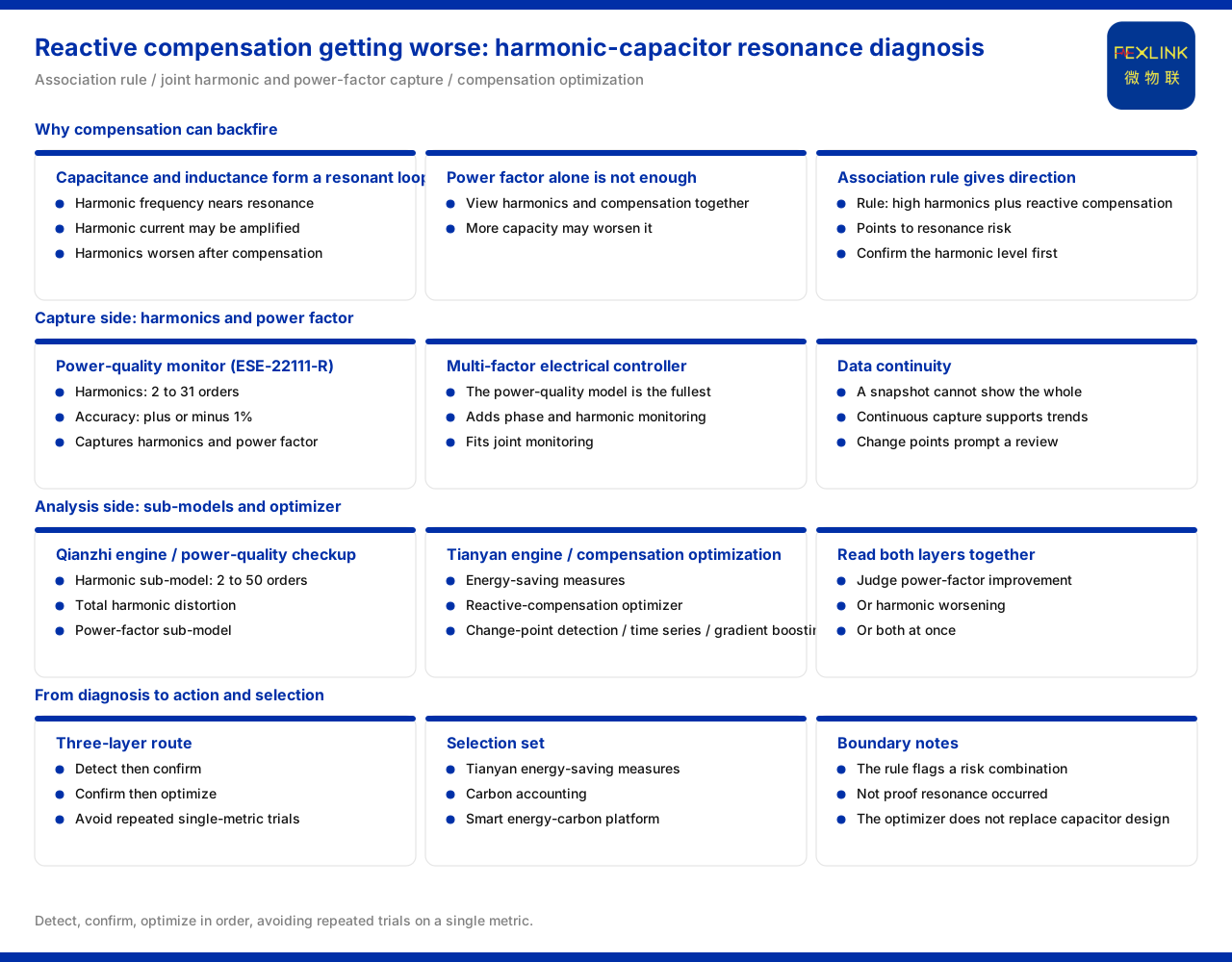
Reactive-power compensation improves the power factor by switching in capacitors, but the capacitor and the inductance in the system form a resonant loop. When the harmonic frequency approaches the resonant frequency of that loop, the harmonic current may be amplified, appearing as harmonics becoming more serious after compensation is switched in. If the compensation capacity is then increased further, the problem may worsen.
Judging whether compensation is "done right" therefore cannot rely only on the power factor but must observe harmonics and the compensation action together. The association rule in the material is designed precisely for this.
The diagnostic clue given by the association rule
Among the association rules of the Wanxiang engine, one rule describes the combination: when high harmonics and reactive-power compensation being switched in occur together, it points to resonance risk. Its value is that it associates two phenomena that are not abnormal when viewed separately, suggesting that the site should not handle them separately but treat them as one group of problems. For the "worse after compensation" scenario, this rule provides a clear direction: confirm the harmonic level first, then confirm whether the compensation action forms an unfavourable combination with the harmonics.
The acquisition side: how harmonics and power factor are taken
On the acquisition side, the ESE power-quality monitor (for example ESE-22111-R) provides harmonic monitoring, with a harmonic order range of 2 to 31 and an accuracy of ±1%, and can be used to acquire harmonics and power factor in a reactive-power compensation circuit. Only by continuously obtaining these two kinds of data does the association rule have input. If only the power factor is watched without harmonics, the interaction between compensation and harmonics is hard to find.
In the multi-parameter electrical intelligent controller series, the power-quality type adds phase monitoring and harmonic monitoring beyond the common monitoring, is the most fully featured, and suits situations where reactive power and harmonics must be monitored jointly.
The analysis side: reactive-power compensation optimisation model
On the analysis side, within the energy-saving countermeasure board of the Tianyan engine, reactive-power compensation optimisation is one of the earlier-opened model directions. Supporting it are the harmonic sub-model and the power-factor sub-model in the power-quality physical examination of the Qianzhi engine: the former focuses on the 2nd to 50th harmonics and the total harmonic distortion, and the latter focuses on the power factor. Only by looking at the two dimensions at the same time can it be judged whether, after compensation is switched in, the power factor improves while harmonics worsen, or both occur.
In terms of algorithms, the core algorithms of the Tianyan engine include change-point detection, time-series prediction and gradient boosting, used to support models such as reactive-power compensation optimisation. The role of these methods is to identify trends and change points from the transaction data and provide a basis for adjusting the compensation strategy.
Selection combination
According to the selection table in the material, the combination corresponding to the energy-saving and carbon-management direction is the energy-saving countermeasure board of the Tianyan engine, the carbon-accounting capability and the smart energy-carbon IoT platform. For the specific problem of reactive-power compensation, the field path is: the power-quality controller or power-quality monitor acquires harmonics and power factor, the physical-examination sub-model of the Qianzhi engine identifies the harmonic and power-factor state, and the reactive-power compensation optimisation model of the Tianyan engine gives an optimisation direction.
From diagnosis to handling
Overall, the diagnostic route for "worse after compensation" can be summarised in three layers: the first layer is association identification, using a rule to confirm whether harmonics and compensation are in an unfavourable state at the same time; the second layer is data confirmation, using the monitoring device to verify the actual levels of harmonic order, content and power factor; and the third layer is optimisation decision, where the reactive-power compensation optimisation model of the Tianyan engine gives an adjustment direction together with the change trend. The three layers advance in order, avoiding repeated trial and error on site based on a single indicator.
Why power factor alone cannot be watched
The power factor is a direct indicator of the compensation effect but is not a sufficient condition for judging whether compensation is reasonable. After compensation is switched in, the power factor may indeed rise, but if harmonic amplification accompanies it, the overall power quality becomes worse instead. Watching only the power factor would misjudge this "superficially improved, substantively worse" situation as success. Only by looking at harmonics and power factor together can the interaction between compensation and harmonics be identified, which is why the association rule emphasises the combined state.
Connection between diagnosis and optimisation
The association rule identifies the direction, the monitoring data confirms the fact, and the optimisation model gives the adjustment idea; the three are progressive. If data confirmation is skipped and the compensation capacity is adjusted directly according to the rule, the judgement may be inaccurate because there is another harmonic source on site; if there is only data without an optimisation model, it is hard to form an executable adjustment suggestion. Connecting the three makes "worse after compensation" no longer a phenomenon with no starting point but a path that can be investigated step by step.
Data continuity and trend judgement
The relationship between reactive-power compensation and harmonics fluctuates with load, and a single snapshot can hardly reflect the whole picture. Only continuous acquisition allows change-point detection and trend prediction to work: when a structural change appears in the harmonic level or power factor, a review of the compensation strategy can be prompted in time. The more continuous the data, the more basis the model has for identifying change points.
From single-point compensation to system observation
A reactive-power compensation problem often involves several circuits, and looking at one compensation point alone easily shows only the local picture. Only by laying harmonic and power-factor monitoring across the relevant circuits can it be judged whether the abnormality is a local phenomenon or a systemic problem. For a distribution system, this observation from point to system is closer to the essence of the problem than a single capacity adjustment.
Several boundaries that need explanation
- An association rule indicates a risk combination and is not equal to resonance having occurred; it must be verified with monitoring data. - The reactive-power compensation optimisation model gives an optimisation direction and does not replace the on-site design of capacitor and reactor configuration. - Harmonic mitigation and reactive-power compensation are two related but different problems and should be assessed separately and handled in coordination.
Scope and limitations
- The content of this article is limited to the existing statements in the product material regarding the association rules of the Wanxiang engine, the energy-saving countermeasure board and core algorithms of the Tianyan engine, the power-quality physical-examination sub-models of the Qianzhi engine, and the power-quality monitor and the multi-parameter electrical intelligent controller series. - The association-rule content, harmonic order and accuracy, sub-model coverage dimensions, core algorithm categories and selection combination are all formulations listed in the material. - This article explains the diagnostic clue and optimisation direction when reactive-power compensation is abnormal; it gives no specific compensation capacity, tuning scheme or mitigation threshold, and actual handling should be determined together with field conditions, equipment specifications and the project scheme. - Other field conditions, installation methods and maintenance cycles not listed in the material are not inferred or promised here.