Direct answer
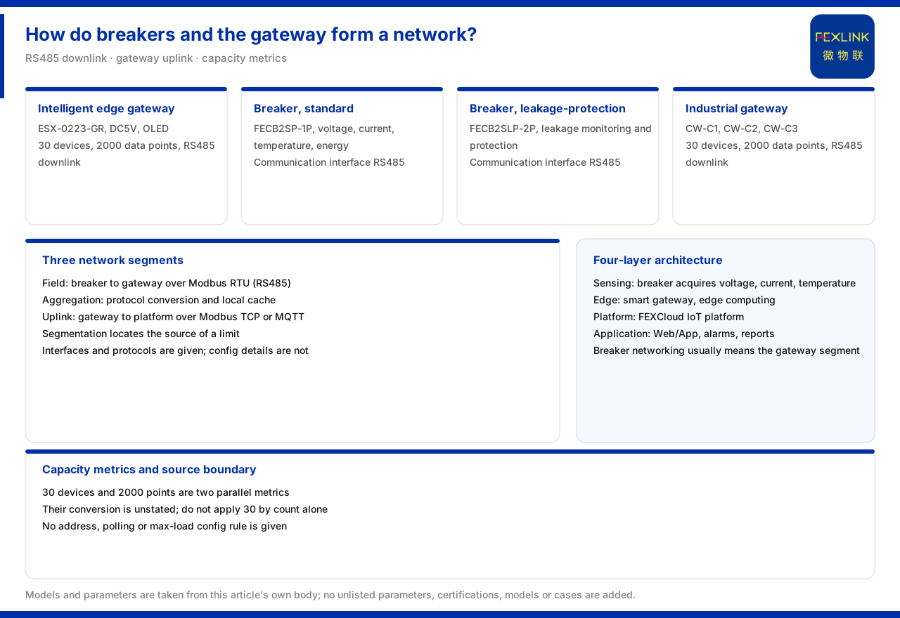
On how breakers and a gateway are networked, the core basis the product knowledge base gives is the capability of the intelligent edge-computing gateway (ESX-0223-GR): an access capability of thirty devices and two thousand data points, RS485 downstream, wired and 4G communication upstream, a DC5V supply, and an OLED display. The communication of both the standard intelligent circuit breaker (FECB2SP-1P) and the intelligent circuit breaker with residual-current protection (FECB2SLP-2P) is listed as RS485, so the breaker side meets the interface condition for mounting on the gateway RS485 downlink. The protocol matrix further shows that device downlink mainly uses Modbus RTU (RS485) and device uplink mainly uses Modbus TCP and MQTT. A networking path can therefore be described: the breakers merge into the gateway over RS485, and the gateway goes uplink to the platform over Ethernet or 4G. The material gives no configuration rule for address assignment, polling period or maximum mounted quantity of breakers under one gateway; it gives only the access capability ceiling of thirty devices and two thousand data points. This article explains this path and the capability ceiling, not the specific configuration.
1. Gateway access capability and interfaces
The product knowledge base lists the model of the intelligent edge-computing gateway as ESX-0223-GR, supplied at DC5V, with an OLED display, an access capability of thirty devices and two thousand data points, RS485 downstream, and wired plus 4G upstream. These parameters are the main basis for judging the networking scale of breakers.
Looking at "thirty devices" and "two thousand data points" separately gives two measurement definitions: by device count, one gateway corresponds to thirty devices; by data point, the total is two thousand points. The material does not state the conversion between the two definitions, and an actual calculation must be made separately according to the data-point definition of the site devices.
2. The breaker communication interface
In its intelligent circuit breaker entry, the product knowledge base lists that both the standard model and the residual-current model support voltage, current and temperature monitoring and energy metering, with the communication column both RS485. The residual-current model additionally includes leakage monitoring and residual-current protection.
The breaker uses RS485 as its communication interface, matching the gateway RS485 downlink in interface type. This is the interface basis for "the breaker can mount on the gateway". The material gives the interface fact, not the address and polling arrangement after mounting.
3. Position in the four-layer architecture
The product knowledge base summarises the monitoring system as perception, edge, platform and application layers. The gateway sits at the edge layer, aggregating perception-layer devices downward and accessing the platform-layer FEXCloud IoT cloud platform upward, above which is the application layer.
Placing the breaker in this architecture, its position is at the perception layer: as a circuit-side monitoring and execution device, it acquires voltage, current, temperature and energy and sends them over RS485 to the edge-layer gateway. This layering explains why "networking" usually means the section from breaker to gateway rather than directly to the platform.
4. Downlink and uplink protocols
The communication protocol matrix of the product knowledge base lists: device downlink mainly uses Modbus RTU (RS485), Zigbee (Modbus) and LoRa; device uplink mainly uses Modbus TCP and MQTT (Ethernet, 4G), with IEC 61850 optional at the gateway level.
Applied to breaker networking, the downlink uses Modbus RTU (RS485) and the uplink uses Modbus TCP or MQTT (Ethernet, 4G). The division of protocols shows the gateway takes on the conversion duty: converting the downlink fieldbus protocol into the uplink network protocol and then sending it to the platform. The breaker itself need not handle the uplink protocol directly.
5. The industrial gateway as a parallel option
Besides the intelligent edge-computing gateway, the product knowledge base also lists several models of the industrial gateway: CW-C1, CW-C2 and CW-C3 all offer thirty devices, two thousand data points and RS485 downlink; their uplinks are respectively Ethernet, Ethernet plus 4G, and RS485 plus Zigbee to Ethernet. This gives a parallel option for breaker networking.
When site uplink conditions differ, for example with wired only or a Zigbee access need, the model can be chosen by the uplink difference. On the downlink side, both kinds of gateway offer RS485, consistent with the breaker interface, which is why both can undertake breaker aggregation.
6. The gateway in the recommended data-center combination
The product knowledge base includes the intelligent edge-computing gateway in the recommended combination for data-center neutral-to-ground voltage and distribution monitoring, alongside the neutral-to-ground voltage monitor and the all-parameter smart meter. This shows the gateway has a clear system position in distribution monitoring, and the data of circuit devices such as breakers and meters all converges to it.
The gateway in the combination is not optional but a necessary link for data to reach the cloud. For breaker networking, this landing point shows that the gateway access capability and uplink method directly determine whether the circuit data can enter the cloud platform for subsequent analysis.
7. Material boundary: no configuration rules
The product knowledge base gives no configuration rule for address assignment, polling period or maximum mounted quantity of breakers under one gateway, only the access capability ceiling of thirty devices and two thousand data points. What can be confirmed is the interface and the capability ceiling; what cannot be confirmed is how many breakers a project may mount and how addresses and polling are arranged.
Keeping the capability ceiling and the configuration rule apart avoids converting "thirty devices" directly into "thirty breakers" without counting their data-point usage. The specific configuration should be calculated separately against the site device list and data-point definitions.
8. Understanding the networking path in segments
A complete networking path can be divided into three segments: the field segment, the aggregation segment and the uplink segment. The field segment is the RS485 connection from breaker to gateway, using Modbus RTU; the aggregation segment is the protocol conversion and local caching inside the gateway; the uplink segment is the Ethernet or 4G connection from gateway to platform, using Modbus TCP or MQTT. The three segments have different duties, and questions should be viewed by segment.
The use of segmenting is to locate the source of a limit. If a field device cannot mount, the issue is in the interface and address of the field segment; if data cannot go up, the issue is in the aggregation or uplink segment. The material lists the interfaces and protocols on which the three segments rest but gives no configuration detail for any segment. This article can therefore help distinguish where a problem lies, not replace a configuration manual.
9. The two capacity definitions
The thirty devices and two thousand data points given by the gateway are two parallel capacity definitions. By device, one gateway corresponds to thirty; by data point, the total is two thousand points. The data-point definitions of a breaker, a meter and a neutral-to-ground voltage monitor differ, and so does their usage.
When planning breaker networking, one should therefore not apply the number thirty by device count alone but also estimate data-point usage. The material gives the capability ceiling; the real mounted quantity depends on the data points each site device actually produces and on whether headroom for future expansion is needed. This article cites the two definitions but gives no conversion formula.
Scope and limitations
First, this article restates only what the product knowledge base lists. The gateway access capability and interfaces, the breaker communication interface, the four-layer architecture position, the protocol matrix, the industrial gateway models and the data-center combination are all cited as recorded.
Second, the material gives no configuration rule for address assignment, polling period or maximum mounted quantity of breakers under one gateway; this article infers no specific networking configuration and gives no address or polling scheme.
Third, the access capability is cited as the listed definition of thirty devices and two thousand data points; this article does not calculate from it the number of breakers in a specific project.
Fourth, the specific networking scheme must be fixed against the site device list, communication conditions and maintenance requirements; this article provides no selection or networking calculation.