Direct answer
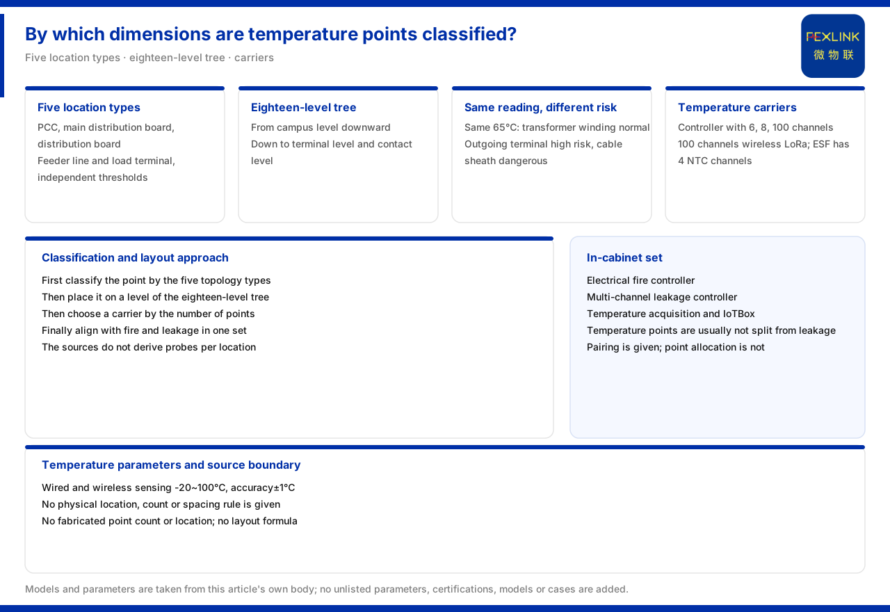
On where temperature sensors should be installed, the product knowledge base does not give a point list but a classification language: location awareness maintains independent thresholds and risk models for five classes of electrical topology location type - PCC point of common coupling, main distribution panel, distribution panel, feeder line and load terminal; and the scenario-location tree provides eighteen levels, down to the wiring-terminal level and the contact-point level. The material also states that the same 65 °C does not carry the same risk at different locations. As for acquisition carriers, the multi-channel temperature intelligent controller (EST-12111-R) provides 6-channel, 8-channel and 100-channel temperature paths, and the electrical fire monitoring and control device (ESF-22110-R) has 4 built-in NTC temperature-monitoring channels. The material gives no physical installation position, quantity or spacing specification for temperature measuring points. This article can therefore answer by what dimensions measuring points are classified, but not how many probes go in each cabinet or on which screw.
1. Five classes of electrical topology location type
The location-awareness entry of the product knowledge base lists five classes of electrical topology location type: PCC point of common coupling, main distribution panel, distribution panel, feeder line and load terminal. The material maintains independent thresholds and risk models for these five classes. The key word is "independent": the location type is not a label but a classification unit that determines the interpretation definition.
Placing the five classes on one supply path reveals their hierarchy: the point of common coupling is the access end, the main distribution panel and distribution panel are the distribution ends, the feeder line is the transmission section, and the load terminal is the end. The attribution of a temperature measuring point can first be located by these five classes, and then the specific point discussed.
2. The eighteen-level scenario-location tree and its finest granularity
Beyond location awareness, the product knowledge base also gives an eighteen-level scenario-location tree, going down level by level from the park level to the seventeenth-level wiring-terminal level and the eighteenth-level contact-point level. This tree provides the hierarchical skeleton of spatial attribution and is a different dimension from the five location classes: one answers "which stage of supply and distribution", the other "which spatial level".
Together, the two dimensions give a measuring point both electrical semantics and spatial semantics. The material pushes the finest level down to wiring terminals and contact points, showing the location language allows a measuring point to be described specifically enough; but this describes classification capability, not an installation specification.
3. The same reading at different locations
The material uses a comparison of the same temperature to show the decisive role of location: the same 65 °C is normal in a transformer winding, a medium risk on a main busbar, a high risk at an outgoing terminal, and a danger on cable insulation. With the same value, the risk interpretation rises in turn by location.
This comparison shows that the measuring-point location itself participates in the risk judgement and is not merely a coordinate of data acquisition. If the point is classified improperly, the same reading may be over-interpreted or missed. The value of the classification language is therefore that it makes the risk meaning of a reading comparable and traceable.
4. Temperature acquisition carriers and channel counts
The product knowledge base lists two carriers for temperature acquisition. The multi-channel temperature intelligent controller provides three specifications of 6, 8 and 100 channels, of which the 100-channel option is a wireless LoRa solution; the electrical fire monitoring and control device has 4 built-in temperature-monitoring channels, uses NTC measurement, ranges from -20~100 °C at an accuracy of ±1 °C, and has an external cable length of one metre.
Placing the two carriers side by side shows the difference in scale and positioning: the former makes multi-channel temperature its main business with more channel choices; the latter makes electrical fire monitoring its main business, with temperature as one component. Selection should follow the number of measured points and the monitoring purpose, not treat one product's channel count as a universal configuration.
5. The ESF in-cabinet combination
In its typical application scenarios, the product knowledge base gives the recommended combination for low-voltage distribution cabinet electrical-fire early warning: the electrical fire monitoring and control device and the multi-channel leakage-current monitoring and control device, together with temperature acquisition and IoTBox. This combination shows that in-cabinet temperature measuring points are usually not separated from leakage monitoring but deployed as a set.
The combination also suggests that measuring-point classification should align with the monitoring purpose: if a point serves electrical-fire early warning, its temperature data appears under the same combination as leakage and other elements; if a point serves only equipment temperature supervision, its attribution and analysis path may differ. The material gives the combination relationship, not the distribution of point quantities.
6. Replacing a scattered point list with location language
The product knowledge base gives no physical installation position, quantity or spacing specification for temperature measuring points. What can be relied on is only the five topology location classes and the eighteen-level location tree as the point-layout classification language. In practice, candidate points can therefore be classified by location type first and then placed at a specific space with the level tree, rather than directly asking for a universal point table.
The advantage is that temperature data becomes comparable between projects: as long as the classification definition is consistent, a main-distribution-panel reading in one project and in another sit under the same semantics, and a comparison is meaningful. The material provides exactly this definition, not a fixed answer replacing on-site judgement.
7. The relation between classification and actual point placement
Chaining the above yields a supported line of thought: first determine by the five electrical topology location classes which stage a point belongs to, then place it at a specific level with the eighteen-level scenario-location tree, then choose the temperature carrier by the number of measured points (6, 8, 100 or 4 channels), and finally bring in-cabinet temperature, electrical fire and leakage into the same combination. The material supports this classification and combination judgement but not the derivation of how many probes each location needs.
Actual points must still be determined against circuit structure, heating mechanism and maintenance accessibility, and those criteria lie outside the factual boundary of the material.
8. The consistency brought by classification definitions
Using the five location classes and the eighteen-level scenario-location tree to classify points has another easily overlooked benefit: temperature data becomes comparable between projects. As long as the classification definition is consistent, the main-distribution-panel readings of project A and project B sit under the same semantics, and only then is a comparison meaningful.
If points are named only by site habit, the same physical location may be called differently across projects, and the data cannot be compared. The classification language of the material is meant to remove this ambiguity. It provides a common definition, not a fixed answer replacing on-site judgement. Actual point placement must still be determined under that common definition by combining circuit structure and maintenance accessibility.
Scope and limitations
First, this article restates only what the product knowledge base lists. The five topology location classes, the eighteen-level scenario-location tree, the location comparison of the same temperature, the temperature-carrier channel counts, the in-cabinet combination and the material boundary are all cited as recorded.
Second, the material gives no physical installation position, quantity or spacing specification for temperature measuring points; this article invents no point quantity or installation position and gives no point-layout formula.
Third, the temperature range and accuracy are cited as listed; this article does not infer probe installation method, protection rating or on-site setting from them.
Fourth, the specific point layout must be fixed against the site circuit structure and maintenance requirements; this article provides no selection or configuration calculation.