Direct Answer
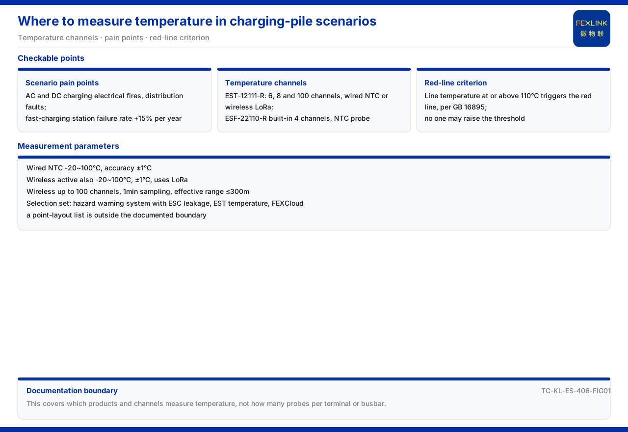
On where temperature should be measured in a charging-pile scenario, the product documentation gives an answer with a clear boundary: it lists the pain points of the charging scenario and the capability of temperature-acquisition products, but it does not give a layout list of specific temperature measuring-point positions in the charging circuit. On the capability side, the EST multi-channel temperature intelligent controller (EST-12111-R) supports wired NTC or wireless LoRa temperature measurement, with channel counts including 6, 8, and 100 channels; the ESF electrical fire monitoring and control device (ESF-22110-R) has 4 built-in temperature-monitoring channels using NTC probes. On the scenario side, the new-energy-vehicle charging system lists the electrical fires of slow and fast charging, distribution-system faults, and a 15% annual increase in fast-charging-station failure rate as pain points, and its system capabilities include charging-safety hazard monitoring, charging-pile operational-efficiency improvement, and a reduction in fire-accident rate. On the criterion side, the red-line guard states that a line temperature reaching or exceeding 110 degrees Celsius triggers the red line, with GB 16895 as the basis.
This article can therefore answer which product measures temperature and what temperature channels and methods exist, but it cannot answer how many probes to place at specific positions such as terminal blocks or busbars, because the latter is outside the documentation boundary.
1. The Pain Points Listed for the Charging Scenario
Under the new-energy-vehicle charging system entry, the documentation lists three pain points: electrical fires of slow and fast charging, distribution-system faults, and a 15% annual increase in fast-charging-station failure rate. The corresponding system capabilities include charging-safety hazard monitoring, charging-pile operational-efficiency improvement, and a reduction in fire-accident rate.
Reading the pain points and capabilities together confirms that temperature monitoring in the charging scenario serves the early detection of electrical fires and distribution faults. Temperature is one direct sign of electrical heating and is therefore related to hazard investigation of the charging circuit, but the documentation does not expand from there to the point level.
From the wording, the pain points face outcomes — fires and faults — while the system capabilities face the process, namely hazard monitoring and operational efficiency. Temperature monitoring belongs to the process-side capability, and its value is expressed through the early detection of abnormal heating.
2. The Temperature Channels and Measurement Methods of the EST
The documentation writes the model rule of the EST multi-channel temperature intelligent controller with three types of encoding: measurement method, channel count, and humidity. The measurement method contains wired NTC and wireless 433, the channel count contains 6, 8, and 100 channels, and humidity contains 1 humidity channel. It places the two probe forms, wired and wireless, and multiple channel steps in the same product line.
The key parameters further give: wired NTC measurement range of -20~100°C at ±1°C accuracy; wireless active measurement likewise -20~100°C at ±1°C, using LoRa communication, a maximum of 100 channels, an adjustable 1-minute sampling period, and an effective distance of no more than 300 meters. These parameters together define the measurement range, scale, and deployment distance of the temperature channels.
3. The 4 Temperature Channels of the ESF
Besides the EST, the documentation lists the ESF electrical fire monitoring and control device with 4 built-in temperature-monitoring channels using NTC measurement, a range of -20~100°C, accuracy of ±1°C, and a 1-meter external lead length. The ESF is positioned for electrical fire monitoring and control, and temperature is only one of its several monitoring elements.
Listing the 4 channels of the ESF alongside the 6, 8, and 100 channels of the EST shows a clear scale difference in temperature channels. Selection should be based on the number of measured points rather than treating one model's channel count as a universal configuration. The ESF's positioning determines that temperature channels are a component, not the whole. If there are many temperature points, the EST's multiple channel steps better suit centralized monitoring; if there are few points and electrical fire monitoring and control is the main purpose, the built-in temperature channels of the ESF can cover them.
4. The Selection Combination for Charging Hazard Early Warning
The documentation lists the selection combination for charging-station and charging-shed hazard early warning as the electrical hazard early-warning system combined with ESC leakage monitoring, EST temperature, and the FEXCloud IoT cloud platform. This combination shows that temperature monitoring is an element parallel to leakage monitoring in charging hazard early warning, not an isolated function.
The presence of the platform means temperature data must be connected to a unified platform to take part in later analysis and alarming. The number and form of temperature channels should be understood in this data chain. Only after temperature data enters the platform can it be compared with leakage monitoring and other elements in the same interface. The choice of channel number and form is therefore preparation of input for later unified analysis.
5. The Line-Temperature Red Line
The red-line guard of the documentation states that a line temperature reaching or exceeding 110 degrees Celsius triggers the red line, with GB 16895 as the basis, and that no person can raise the threshold. This article cites this threshold and the standard basis, but a red line and a product parameter must be distinguished: the red line is a compliance threshold defining a non-bypassable boundary, not evidence that a temperature product's action value has been set to that threshold.
For the charging-pile scenario, the meaning of the line-temperature red line is that it gives the compliance criterion on the temperature side. Whether a temperature product's range covers that threshold is one prerequisite for judging whether it can serve such a scenario.
6. Returning from Channel Count to Scenario Judgment
Linking scenario, channels, and red line yields a judgment order supported by the documentation: first confirm whether the scenario requires temperature monitoring — the new-energy-vehicle charging system lists pain points such as electrical fires and distribution faults, showing temperature is a related element; then confirm the available temperature channels — the EST multi-channel temperature intelligent controller provides 6, 8, and 100 channels, and the ESF electrical fire monitoring and control device provides 4; and finally confirm the criterion — the line-temperature red line is 110 degrees Celsius, based on GB 16895.
In this order, the choice between wired and wireless is based on on-site wiring conditions and deployment distance. Wired NTC and wireless LoRa share the same -20~100°C measurement range and ±1°C accuracy, the wireless scheme has an effective distance of no more than 300 meters, and the sampling period is adjustable at 1 minute. Comparing these parameters with the field conditions allows a choice between the two forms.
7. The Documentation Boundary of Measuring-Point Position
On where exactly to measure, the documentation gives only the pain points and the temperature channel capability of the EST and ESF in the charging-pile scenario, and does not give a layout list of specific temperature measuring-point positions in the charging circuit, such as terminal blocks and busbars. This article therefore does not invent point counts and installation positions.
Actual layout requires separate judgment against the circuit structure and heating mechanism, and those criteria are outside the factual boundary of the documentation. This article provides the available temperature channels and the red-line criterion, not a ready-made point list.
Scope and Limitations
First, this article restates only what the product documentation lists. The charging-scenario pain points, the EST model rule and key parameters, the ESF temperature configuration, the selection combination, and the temperature red line are cited as written.
Second, the measurement range, accuracy, channel counts, and probe forms of the EST and ESF are cited as listed; this article does not infer their installation method, protection rating, or field setting.
Third, the value of the line-temperature red line and its standard basis are cited as listed; this article does not conclude that any temperature product has been set to that threshold.
Fourth, this article gives no layout list or point formula for specific temperature measuring points in the charging circuit, because that content is outside the factual boundary of the product documentation.