Data center servers reboot intermittently and the network drops packets, yet the usual checks — dual utility feeds, UPS output, PDU branch loading, and the server's own logs — all read normal. The fault is never pinned down, and reboots continue. Between "routine power checks are normal" and "the IT equipment still misbehaves," what is often missing is not a finer inspection but a quantity that has been overlooked all along: neutral-to-ground (N-G) voltage. When an abnormal potential difference appears between a critical circuit's neutral and ground, the reference potential seen by IT equipment is lifted, and the result can surface as reboots or packet loss that are hard to reproduce. Only parameters and combinations listed in the knowledge base are used; no N-G limits, accuracy figures, or cases are invented.
1. Why conventional power checks come up empty
After a reboot, the first instinct is to check power: is utility voltage stable, has the UPS transferred, is any PDU branch overloaded, has the power supply alarmed? These answer "was the supply interrupted, and is the voltage high enough?" They explain many reboots, but not the other class: supply uninterrupted, voltage in range, yet the equipment still misbehaved during communication or computation.
Routine checks concentrate on the voltage between phase and neutral, while equipment depends on a stable reference potential. If the neutral-to-ground potential difference rises abnormally, the zero-potential reference the equipment receives is no longer clean; even with a normal phase voltage, logic circuits and communication interfaces can still be disturbed. Such events are intermittent, load-related, and hard to reproduce, so they are easily written off as "a fault in the equipment itself." Closing this gap requires treating N-G voltage as a measurable, recordable parameter.
2. Where neutral-to-ground voltage comes from and how it disturbs IT equipment
In distribution engineering, N-G voltage is the potential difference between the neutral point and ground. It can arise from the voltage drop produced by neutral current through conductor impedance, from the impedance of the grounding system itself, from potential differences introduced by multiple grounding points, and from three-phase load imbalance. None of these is rare in a data center: many single-phase loads, high harmonic currents, densely packed racks, and complex grounding paths all push the N-G potential difference away from the ideal state.
For IT equipment, the difference affects the reference, not the energy. Signal ground of servers, switches, and similar equipment is bonded to the rack and room grounding system. When the N-G difference rises, an unwanted difference can appear between equipment ports and compromise communication integrity. It need not appear immediately as a crash; it can show up as packet loss, link flapping, or an occasional reboot — a symptom that, being atypical and coexisting with a normal supply, makes N-G voltage an easily skipped link in the troubleshooting chain. Continuous monitoring adds an observable line of evidence for this class of problem.
3. What to monitor and where: continuous sampling on critical circuits
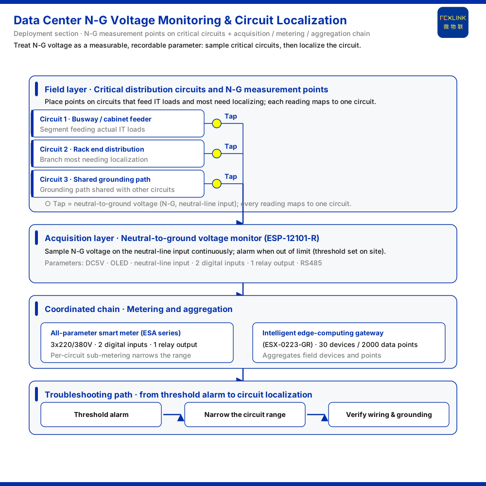
N-G voltage rises only on specific circuits at specific moments, so a one-off multimeter check rarely catches it. The approach: deploy a neutral-to-ground voltage monitor (ESP-12101-R) on critical circuits and sample N-G voltage on the neutral-line input continuously. Per the parameter table in the knowledge base, the monitor runs on DC5V, uses an OLED display, takes a neutral-line voltage input, and provides 2 digital inputs and 1 relay output, with RS485 communication. These interfaces let it display readings locally, accept field signals, and feed data upward over RS485.
The choice of critical circuit determines whether the data is useful. What deserves continuous attention is usually the segment from which IT equipment actually draws power: the feeders of busway or distribution cabinets, the end distribution of important racks, and branches sharing a grounding path with other circuits. Placing points there lets the sampled N-G voltage line up in time with a reboot of a particular group of devices. The layout need not be numerous; it must be locatable — every reading should map to one clearly identified circuit.
4. From threshold alarm to circuit localization: a three-layer chain
A single point answers only "N-G voltage is high here." Answering "which circuit, and which group of equipment" requires linking acquisition, metering, and aggregation. The recommended combination for data center N-G voltage or distribution monitoring in the knowledge base is exactly the coordination of the neutral-to-ground voltage monitor (ESP-12101-R), the all-parameter smart meter (ESA series, example model ESA-22111-R), and the intelligent edge-computing gateway (ESX-0223-GR).
The N-G voltage monitor samples N-G voltage on critical circuits and alarms once a reading exceeds a set threshold — set on site to local distribution conditions, with no specific value drafted here. The all-parameter smart meter handles sub-metering for the same area; the knowledge base shows the whole series at 3×220/380V with 2 digital inputs and 1 relay output, so it can obtain per-circuit data and help narrow the abnormal range. The intelligent edge-computing gateway aggregates these field devices upstream; the knowledge base gives its access capability as 30 devices / 2000 data points, suitable for carrying multiple circuits, meters, and monitoring points in one gateway.
The path thus turns from "why did the server reboot" into a traceable causal chain: the monitor detects an out-of-limit N-G voltage and alarms; circuit-level data from the meter and gateway helps identify the branch and the equipment states it coincides with; operations then verifies that segment's wiring, loading, and grounding. Localization's value is not a conclusion but compressing an intermittent fault into a limited set of candidate circuits.
5. Parameters and selection at a glance
Key parameters of the three device classes, as listed in the knowledge base.
| Device (model) | Key parameters listed in the knowledge base | |:--|:--| | Neutral-to-ground voltage monitor (ESP-12101-R) | Power DC5V; display OLED; voltage input neutral-line input; 2 digital inputs; 1 relay output; RS485 communication | | All-parameter smart meter (ESA series) | Voltage 3×220/380V; 2 digital inputs; 1 relay output | | Intelligent edge-computing gateway (ESX-0223-GR) | Access capability 30 devices / 2000 data points |
These are only the parameters listed in the corresponding knowledge base entries, excluding unlisted indicators such as the N-G voltage operating threshold, measurement accuracy, and alarm latency. Those values are to be determined during project selection and setting; this article infers none of them.
6. Bringing N-G voltage into routine monitoring
Start with three steps. First, define measurement points: map the important circuits and place continuous monitoring on the few segments from which IT equipment actually draws power and where localization matters most. Second, define the action: who responds once N-G voltage exceeds the threshold and how it is linked; the monitor's relay output and the gateway's data can both feed an alarm workflow. Third, keep evidence: record N-G voltage on each circuit so an occasional reboot can later be compared against historical curves rather than memory.
Data center design and grounding requirements involve relevant standards. In the knowledge base, GB/T 16895 is referenced under entries for the line-temperature and insulation-resistance red lines; GB 50174 (Data Center Design Specification) does not appear in the knowledge base body and is treated as "pending match." Any clause-level reference must first be matched within the 408-standard library; this article quotes no clause text and states no limits under a standard's name without matching.
Scope and limitations
- This article addresses only how, when servers reboot intermittently or drop packets while routine power checks are normal, to bring N-G voltage into monitoring and localize a circuit. It does not cover harmonic mitigation, imbalance mitigation, grounding retrofits, or cost estimates. - All product parameters are limited to the corresponding knowledge base entries: the neutral-to-ground voltage monitor (ESP-12101-R) with DC5V, OLED, neutral-line input, 2 digital inputs, 1 relay output, and RS485; the all-parameter smart meter (ESA series) with 3×220/380V, 2 digital inputs, and 1 relay output; and the intelligent edge-computing gateway (ESX-0223-GR) with 30 devices / 2000 data points. - The recommended combination — neutral-to-ground voltage monitor + all-parameter smart meter + intelligent edge-computing gateway — comes from the data center N-G voltage / distribution monitoring row of the knowledge base; it does not extend other combinations or topologies. - This article gives no N-G voltage operating threshold, measurement accuracy, or alarm latency, nor any performance indicator such as reboot rate or localization accuracy. Thresholds and settings should be determined by the project site according to its own distribution conditions. - Clause-level references to GB 50174 and GB/T 16895 must be matched within the knowledge base's 408-standard library before use. GB 50174 does not appear in the body of the knowledge base and is stated within a "pending match" boundary; this article quotes no clause content. - This article claims no product parameter, certification, case, or effect not listed in the knowledge base, and does not extrapolate beyond that scope.