The central conflict in operating-room power supply is not whether to protect, but whether protection must cut the power. An ordinary residual current device (RCD) trips and disconnects the circuit; the equipment connected in an operating room must not lose power while surgery is in progress. The direct answer: healthcare locations with high power-continuity requirements use IT isolation systems, in which a first insulation fault does not disconnect the supply but only raises an alarm, preserving continuity for life-support equipment. Insulation monitoring should therefore be performed and brought into centralized monitoring, rather than installing an ordinary RCD that trips.
1. Direct Answer: Operating Rooms Need "Alarm Without Power Cut"
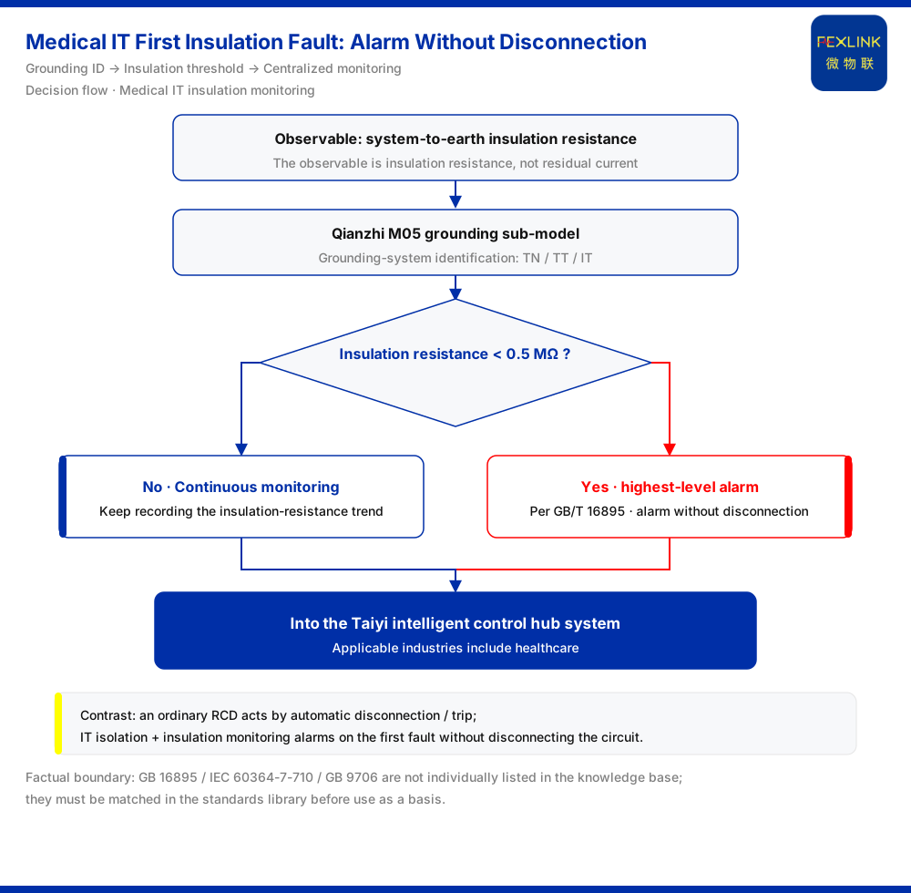
The problem becomes clear once it is split into two actions. An ordinary RCD acts by "disconnecting the circuit as soon as residual current exceeds the limit." An IT isolation system with insulation monitoring acts by "raising an alarm as soon as insulation degrades, without disconnecting the circuit."
Operating rooms choose the latter not because RCDs are unreliable, but because the consequence of their action conflicts with what the operating room requires: if power is tripped by an insulation fault during surgery, the risk from the interruption is higher than that of the first insulation fault itself. What the operating room needs is therefore not "a more sensitive trip" but "knowing where the fault is without tripping."
In one sentence: an RCD addresses "how to cut power after a fault," whereas IT-system insulation monitoring addresses "how to stay powered and still see the fault."
2. Why RCD Trip Logic Conflicts With Operating Rooms
An RCD works on the basis of residual current: when the phase and neutral currents in a circuit are unbalanced, the residual is judged to be leakage or fault current, and the device trips once the operating value is reached. Its design goal is explicit — to remove electric-shock and electrical-fire risk by cutting the supply.
In an ordinary distribution circuit this logic holds because a power cut is acceptable. But an operating room carries equipment that cannot be interrupted during surgery, so a power cut transfers risk from "electrical fault" to "interruption of medical service." For such locations, "fault means power cut" is not protection; it is another kind of incident.
The question is therefore not "is the RCD good enough," but "is a protection whose only action is tripping suitable for a location where power must not be cut?"
3. The Key to IT Isolation Systems: Why the First Insulation Fault Does Not Trip
The core feature of an IT system is that no direct low-impedance path is established between the supply and earth. Thus, when a first insulation fault occurs, the fault current has no low-impedance return path, the residual current in the circuit is very small, and it is insufficient to drive ordinary residual-current protection.
The system can therefore continue to supply power, and surgery is not interrupted by the first insulation fault. This is precisely why operating rooms choose IT isolation systems: to decouple "fault" from "power cut."
But not disconnecting does not mean not handling. The insulation fault objectively exists; if it is not detected and cleared, a second fault may form a low-impedance path, causing overcurrent or a short circuit, at which point a power cut becomes unavoidable. The premise of the IT system's "no trip" is that there must be a monitoring means able to detect the first fault immediately — this is the reason insulation monitoring exists.
4. The Insulation Monitoring Evidence Chain: The Insulation-Resistance Red Line and <0.5 MΩ
An insulation monitoring device converts "is the insulation intact" into a comparable value: insulation resistance. It continuously measures the system's insulation resistance to earth and raises an alarm when insulation degrades, allowing operations to locate and handle the fault before a second fault develops.
According to the knowledge base, when insulation resistance is <0.5 MΩ, the insulation-resistance red line triggers the highest-level alarm, on the basis of GB/T 16895. This rule belongs to the red-line guards — there are five in total, they cannot be bypassed, and no one can raise the threshold.
Understanding the insulation-resistance red line requires distinguishing its nature from that of an RCD. The action of an RCD is "automatic disconnection"; the action of the red line is "triggering the highest-level alarm." The former directly changes the power-supply state; the latter exposes insulation state as evidence and drives people to act. For an operating room, this order of "alarm first, handle second" is exactly what reconciles power continuity with fault controllability.
In the six-level alarm system, the highest-level alarm corresponds to BJ2 (0–19 points). Note that this article states only the red line's trigger condition, threshold, and basis as written in the knowledge base; it does not extrapolate specific standard clauses or infer on-site handling time limits.
5. Why TN/TT/IT Must Be Identified First: the M05 Grounding Sub-model
For insulation monitoring to run correctly, one must first know which grounding system is faced. For the same drop in insulation, the fault loop, residual-current behavior, and monitoring focus differ among TN, TT, and IT grounding systems.
The Qianzhi engine's basic vital-signs sub-model M05 is responsible precisely for grounding-system identification: TN/TT/IT identification (the knowledge base). Only after the grounding type is identified do insulation monitoring data have a correct interpretation premise and does the red line's trigger become meaningful — otherwise, one detects a value of "low insulation resistance" without knowing which type of circuit and which risk it corresponds to.
This also explains why "installing a residual-current protector" cannot replace "performing insulation monitoring": the former does not distinguish grounding systems and acts only on residual current, not insulation resistance.
6. From a Standalone Instrument to Centralized Monitoring: the Taiyi Intelligent Control Hub System
Insulation monitoring in an operating room should not stop at a local audible-and-visual alarm. An insulation fault's value lies in being fully recorded, promptly seen, and brought into unified assessment.
According to the knowledge base, the applicable industries of the Taiyi intelligent control hub system include healthcare, that is, it applies to medical scenarios. It organizes processing in a seven-stage pipeline, in which L3 is standard verification (the red-line pre-check): the red-line pre-check runs before the Qianzhi sub-model computation, and once a red line is triggered it directly outputs the highest-level alarm. The insulation-resistance red line is one of the rules verified at this layer.
This brings two practical benefits. First, once insulation monitoring data enters the unified link, the trend of insulation resistance is recorded continuously rather than noticed only at a trip or local alarm. Second, the red-line trigger is placed before analysis, meaning the insulation red line is a hard constraint that does not participate in subsequent weighted compromise.
7. Interpretation Points and Field Checklist
Condensing the above into an actionable checklist:
- Location judgment: confirm whether the target location is one where power must not be cut during a procedure; if so, assess an IT isolation system with insulation monitoring, not an ordinary RCD. - Monitoring object: the observed quantity of insulation monitoring is insulation resistance, not residual current; do not substitute the action result of residual-current protection for an insulation-state judgment. - Threshold and rule: insulation resistance <0.5 MΩ triggers the insulation-resistance red line and the highest-level alarm, on the basis of GB/T 16895, and is a non-bypassable red line. - Grounding identification: have M05 complete TN/TT/IT identification first, then interpret the insulation monitoring data. - Centralized management: bring insulation monitoring into the unified link of the Taiyi intelligent control hub system, so that the insulation-resistance red line takes effect in the L3 pre-check.
Scope and Limitations
First, the core boundary of this article is the knowledge base: the M05 grounding sub-model's TN/TT/IT identification, the insulation-resistance red line's trigger condition and threshold, and the fact that the applicable industries of the Taiyi intelligent control hub system include healthcare.
Second, the insulation resistance threshold of <0.5 MΩ and the phrase "on the basis of GB/T 16895" are limited to the insulation-resistance red-line entry in the knowledge base; this article does not reproduce or extrapolate the original content of other standard clauses.
Third, standards for medical locations such as GB 16895, IEC 60364-7-710, and GB 9706 are not individually listed in the knowledge base and must be matched in the knowledge base's 408-standard library before they can serve as a basis (a controlled boundary); this article makes no standard-compliance determination on that basis.
Fourth, the knowledge base does not individually list a dedicated medical IT-system insulation monitoring model, and selection must be confirmed manually; this article does not infer specific product models, parameters, certifications, or project applicability.
Fifth, this article explains the principles and evidence chain of insulation monitoring in medical IT systems and does not constitute a power-supply conclusion for any specific medical location; where engineering design is involved, current standards and site conditions should govern, and a qualified professional party should verify.