Direct Answer
A running cable needs temperature sensors installed with live (no-outage) construction. How should it be done safely and in compliance? The answer — key points for live retrofit: use insulated tools and work per circuit with local sectional de-energization; fix sensors with clips/ties at joints and terminations; number each section as it is retrofitted so circuit correspondence is ensured; maintain the safety distance throughout, with two-person supervision for critical work; first trial-install on low-voltage, low-risk circuits before rolling out.
At one industrial park's 10kV cable tunnel, temperature measurement was added live: a 400V low-voltage circuit was first trial-installed (clip fixing, circuit numbering, signal testing), and after confirming the process it was rolled out to 10kV circuits; the retrofit followed "one section, one stop" (single-circuit local de-energization), two-person supervision, and insulated-tool work; sensors were clip-fixed at joints and terminations. After the retrofit, temperature data uploaded normally with no safety incident. Retrofit core: safety measures, fixing method, circuit numbering — staged trial, supervision in place, retrofit without affecting operation.
Because:
- Live work carries electric-shock risk: insulated tools + safety distance + supervision are all indispensable; - The fixing method determines measurement accuracy: clips/ties at joints and terminations (hot-spot locations); - Circuit numbering determines data attribution: number each section as retrofitted so circuits stay matched; - Staged trial determines rollout safety: verify the process on low voltage first, then roll out to high voltage.
Key insight: "supervision + insulation + numbering + trial" — the four safeguards of live cable retrofit. Safety measures first, process verified before rollout — the retrofit is both safe and standardized.
At one plant, temperature sensors were installed on a live 10kV cable (without a low-voltage trial or numbering); during the work a sensor almost touched an adjacent phase (insufficient safety distance), nearly causing a short circuit; confused circuit numbering later made data not match equipment. Rectification: rework per the standard process (two-person supervision, insulated tools, low-voltage trial first, section-by-section numbering). Lesson: nonstandard process causes incidents — safety measures and numbering management are the bottom line of live retrofit.
1. Work-Safety Measures
Step one: how to ensure safety.
Core measures: - Two-person supervision: at least two people for critical work (worker + supervisor); - Insulated tools: insulating gloves, mats, operating rods; - Safety distance: maintain the code distance from live parts; - Local de-energization: single-circuit work can be locally de-energized (without affecting other circuits).
Work procedures: - Before: confirm the circuit, outage scope, voltage test and grounding; - During: work with insulated tools, do not touch live parts, supervisor in place; - After: confirm restoration, clean up, record and sign; - Emergency readiness: insulation first aid, breaker contingency (drills).
Environmental notes: - Cable tunnels/wells: ventilation check (oxygen/hazardous gas); - Humid environments: anti-slip, anti-shock (insulating mats); - Hot environments: limit work duration (heat safety); - Night work: adequate lighting (see circuits and labels).
Key insight: "supervision + insulation + distance + local de-energization" — the safety four-piece set for live work. Every item is life-critical; none can be skipped.
2. Sensor Fixing Methods
Step two: how to fix for accuracy.
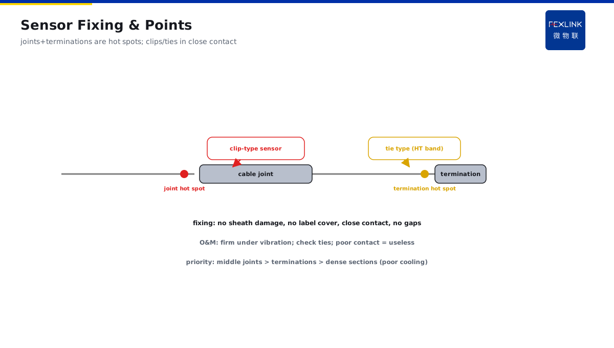
Fixing locations: - Cable joints: hot-spot-prone (joint resistance is high); - Cable terminations: weak insulation/connection points; - Middle joints: the focus for long cables; - Bending/dense sections: poor heat-dissipation areas (optional).
Fixing methods: - Clip type: dedicated clips (no cable damage); - Tying type: high-temperature ties (firm, no sliding); - Adhesive type: thermal adhesive (surface contact); - Notes: do not damage the outer sheath, do not cover labels.
Contact quality: - Sensor in close contact with the cable surface (key to temperature accuracy); - Avoid gaps (air insulation causes reading deviation); - Firm fixing (no displacement under vibration); - Periodic checks (tie aging/loosening).
Key insight: "hot-spot location + close contact + firm fixing" — the three conditions for accurate temperature measurement. Joints and terminations are the focus; poor contact means the installation is useless.
3. Circuit Numbering and Ledger
Step three: how to guarantee data correspondence.
Numbering principles: - Number each section as it is retrofitted (in sync); - Number corresponds to the circuit (sensor ↔ cable ↔ breaker); - Clear labels (tags/nameplates/color codes); - Ledger in sync (number/location/model/date).
Ledger content: - Circuit number and cable name; - Sensor model and installation location; - Corresponding switchgear/terminal information; - Installation date and construction records.
Common problems: - Confused numbering: data does not match equipment (useless measurement); - Missing ledger: maintenance cannot find points; - Fallen labels: on-site identification fails; - Out-of-sync retrofit: number/equipment mismatch.
Key insight: "retrofit one section, number one section, record one section" — the iron rule of circuit management. Numbering + labels + ledger — clear data attribution, retrofit without chaos.
4. Signal-Path Testing
Step four: how to confirm it works once installed.
Test content: - Sensor power/communication normal; - Temperature data uploaded to the platform; - Circuit number corresponds to the platform point; - No crosstalk between adjacent circuits (independent data).
Test methods: - Test immediately after retrofit (per-section verification); - Compare with known temperature (ambient reasonableness); - Platform point verification (number ↔ data); - Trial-run observation (initial data stability).
Common-problem troubleshooting: - No data: power/communication/configuration issue; - Abnormal data: poor contact/sensor fault; - Data crosstalk: number mismatch/frequency conflict; - Point mismatch: ledger differs from actual.
Key insight: "per-section test + platform verification" — a mandatory acceptance action. Data uploaded, numbering matched — installed and usable, no hidden defects.
5. Staged Construction Sequence
Step five: how to arrange most stably.
Staging principles: - Low voltage first, then high (verify the process before rollout); - Single point first, then batch (single-circuit trial); - Simple first, then complex (easy circuits first); - Avoid peak load (minimum impact on operation).
Construction sequence: - Batch 1: 400V low-voltage trial (verify the process); - Batch 2: 10kV general circuits (roll out the mature process); - Batch 3: 10kV critical circuits (careful work); - Throughout: one section one stop, supervision in place, numbering in sync.
Risk control: - Safety briefing before each batch; - Evaluation after each batch (problem review); - Interval between batches (time to digest issues); - Critical circuits off-peak (reduce operation impact).
Key insight: "trial first, roll out later, in batches" — the rhythm of live retrofit. Low-voltage verification, high-voltage rollout — each batch closes its loop, risk controlled.
6. Product Landing: EST Multi-Channel Temperature Smart Controller
FEXLINK products land cable-temperature retrofit:
- EST Multi-Channel Temperature Smart Controller (wireless LoRa temperature) : wireless sensors, no cabling (simple retrofit); - Clip/tying installation: fits joints and terminations; - Multi-circuit management: online numbering and ledger; - Signal self-check: sensor status and data-quality monitoring.
Design principle in one sentence: "safe work, standard fixing, clear circuits." Supervision + insulation + numbering + trial — the cable-temperature retrofit is safe and standardized.
Pre-work checklist: - Safety: two people in place (worker + supervisor); insulated tools complete (gloves/mats/rods); voltage test confirmed in the work area; ventilation check (tunnel/well); - Circuit: work circuit and outage scope confirmed; adjacent-circuit labels checked; local de-energization scope defined; - Materials: sensors/clips/ties/labels ready; models match the cable structure; ledger template ready; - Process: this section's numbering plan clear; signal-test method confirmed; emergency readiness (breaker contingency) in place.
7. Common Retrofit Misconceptions
1. Live work without supervision: single-person work to save manpower. Consequence: electric shock/accidental contact with no one to respond. Correct: two-person supervision for critical work. 2. Random sensor fixing: not in contact with the cable surface. Consequence: temperature deviation/data distortion. Correct: clips/ties + close contact at hot-spot locations. 3. No numbering, no ledger: installed without records. Consequence: data does not match equipment. Correct: retrofit one section, number one section, record one section. 4. Skipping the low-voltage trial: going straight to high voltage. Consequence: process problems amplified at high voltage. Correct: verify on low voltage first, then roll out. 5. No testing after installation: no signal-path verification. Consequence: useless installation (data not uploading). Correct: per-section test + platform verification.
Scope and Limitations
This article provides the key points for live retrofit of cable on-line temperature measurement (work safety, sensor fixing, circuit numbering, signal testing, staged construction) for temperature-monitoring retrofits on running cables (tunnel/trench/tray). Specific work must follow on-site voltage levels, environmental conditions, and safety codes; live work requires appropriate qualifications and work-permit management; sensor selection and installation must match the cable structure (no damage to the outer sheath). All cases are anonymized (a certain industrial park/a certain plant) and do not refer to any specific customer.