
The difficulty of lightning-protection monitoring for ancient buildings and heritage sites
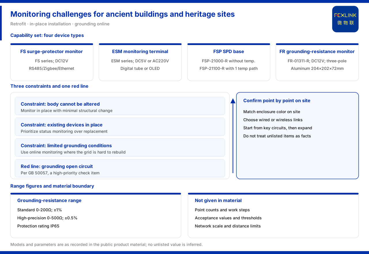
Direct answer: ancient buildings and heritage sites are existing structures, and the core difficulty of lightning-protection monitoring for them is that the structure itself must not be damaged. The material lists surge protective device state monitoring (existing SPD retrofit) as a typical application scenario, with a recommended combination of the FS surge protective device monitor, the ESM intelligent lightning-protection monitoring terminal and the FSP SPD lightning-protection base. The three devices each have a role: the FS device carries state acquisition for the protective device itself, the ESM device carries multi-parameter aggregation, and the FSP base provides the in-place mounting form that works with existing protective devices. Around grounding, the FR grounding resistance monitor provides online monitoring, and the grounding resistance monitoring unit covers two ranges, 0-200 Ω and 0-500 Ω. Monitoring must be completed without replacing existing devices and without major structural work, and this is the fundamental constraint that distinguishes an ancient-building scenario from a new-build project.
Difficulty one: the structure itself cannot be damaged, so monitoring can only be added in place
The walls, timber frames, painted surfaces and roofs of ancient buildings and heritage sites usually carry heritage value, and any change to their original state needs careful assessment. Lightning-protection monitoring therefore cannot take the route of replacing the whole protective device; it should choose the method that disturbs the structure as little as possible. According to the material, the FS surge protective device monitor series all use DC 12 V supply, come in a lightning-monitoring enclosure available in grey, black or white, and support RS485, Zigbee and Ethernet communication. Low-voltage supply and a modular enclosure are the basis for adapting to the weak-current conditions of an ancient building and for easy in-place installation.
A low supply voltage lightens the burden of taking power and laying cable; a choice of enclosure colour makes it easier to coordinate with existing cabinets, boxes or interior colours; and multiple communication methods let the site choose between wired and wireless. These parameters are not complicated in themselves, but together they match the requirements of an existing retrofit: little change, easy coordination and simple deployment. Which enclosure and communication method a particular ancient building uses still has to be confirmed against site conditions.
Difficulty two: protective devices are already in place, so retrofits start with state monitoring
The difference between an existing site and a new one lies in the constraints. A new project can decide device models and wiring methods at the design stage; an existing project can only add on top of the existing distribution structure, and the smaller the change, the better. The value of state monitoring lies precisely here: it does not replace the protective device itself, but adds acquisition of state alongside it.
The recommended combination given by the material covers three roles. The FS surge protective device monitor handles state acquisition for a single point or a local protective device; the ESM intelligent lightning-protection monitoring terminal handles all-parameter situations needing centralised monitoring, is the all-parameter version, offers a supply choice of DC 5 V or AC 220 V, uses a digital-tube or OLED display, and integrates digital inputs, grounding state and lightning-strike count; and the FSP SPD lightning-protection base provides the mounting form that goes with the protective device. In a retrofit, one can start with the protective devices on the key circuits and then extend to the whole site as needed.
Difficulty three: grounding conditions are constrained and the grounding grid is hard to modify
For an ancient building, grounding conditions are often another practical constraint. Courtyard ground, underground remains and the surrounding environment usually do not allow large-scale excavation, so the grounding grid is hard to modify. According to the material, the FR grounding resistance monitor (for example FR-01311-R) uses DC 12 V supply, outdoor installation, three-electrode measurement and RS485 communication, with an aluminium enclosure measuring 204 × 202 × 72 mm. The combination of outdoor use and the three-electrode method suits deployment near the grounding grid, turning whether grounding is still usable from a one-off measurement into continuous online observation.
On range and accuracy, the material gives the formulation of the grounding resistance monitoring unit: the standard type is 0-200 Ω with an accuracy of ±1%; the high-precision type is 0-500 Ω with an accuracy of ±0.5%; and the protection rating is IP65. Range and accuracy correspond to different measuring-point conditions, and selection should match the actual grounding-grid resistance on site, avoiding a mismatch between range and accuracy.
The two configurations of the SPD lightning-protection base
The FSP SPD lightning-protection base offers two representative configurations: FSP-21000-R does not include temperature monitoring, while FSP-21100-R includes one temperature path; both are powered by AC 220 V, use a digital-tube display and communicate over RS485. The difference between including and not including temperature determines whether the base can provide temperature state locally.
Which one to choose depends on whether the monitored protective device needs the temperature dimension. If the existing protective device already has independent temperature monitoring, the base can omit temperature; if not, the temperature version can fill in that item. The two configurations share the same supply and communication form, so the wiring change during replacement or expansion is relatively controllable. The idea of adding monitoring in place without replacing the device itself is put into practice exactly here.
The choice of communication and supply
Supply and cabling conditions at an existing retrofit site are often uneven. From the supply formulations given by the material, the FS surge protective device monitor is DC 12 V, the ESM intelligent lightning-protection monitoring terminal can choose between DC 5 V and AC 220 V, the FSP SPD lightning-protection base is AC 220 V, and the FR grounding resistance monitor is DC 12 V. A scheme should confirm each device against the power available at its location rather than planning uniformly around one supply.
On communication, the FS surge protective device monitor supports RS485, Zigbee and Ethernet, while the FR grounding resistance monitor supports RS485. If wired network already exists on site, wired can be preferred; if cabling is difficult, a wireless method can be considered. The material gives no networking scale or distance limits for the different communication methods.
One safety red line that cannot be bypassed
In its safety rules, the material lists abnormal open circuit of grounding resistance as a red-line condition that cannot be bypassed, with the basis pointing to GB 50057. Grounding is the last reliance of lightning protection and electrical safety; once the grounding path is abnormally open, the discharge path does not hold even if the protective devices in front are in normal state. For ancient buildings and heritage sites this item is especially critical, because the grounding grid is both hard to modify and hard to excavate and re-check frequently. The correct approach is to make grounding resistance observable online with the grounding resistance monitor, moving open-circuit abnormalities from after-the-fact discovery to online visibility, and then to combine this with on-site review.
On-site check list
1. Confirm the structural protection requirement and define the permitted construction scope. 2. Take stock of the existing devices: model, mounting method and existing monitoring channels. 3. Place the capabilities by combination, using the FS monitor, the ESM terminal and the FSP base as the reference. 4. Include online grounding monitoring with the FR monitor, matching range and accuracy to the on-site resistance. 5. Handle the open-circuit risk first, based on GB 50057, and keep observing online. 6. Do not cross the material boundary: counts, steps and acceptance formulations not given should be confirmed separately on site and recorded.
Summary
The difficulty of lightning-protection monitoring for ancient buildings and heritage sites can be summed up as three constraints and one set of capabilities. The three constraints are: the structure cannot be damaged, so monitoring can only be added in place; the existing devices are already in place, so the retrofit starts with state monitoring; and grounding conditions are constrained, so the grounding grid is hard to modify. The set of capabilities is: the FS surge protective device monitor carries state acquisition for the protective device itself, the ESM intelligent lightning-protection monitoring terminal carries multi-parameter aggregation, the FSP SPD lightning-protection base provides the in-place mounting form, and the FR grounding resistance monitor carries online grounding-grid monitoring; the grounding resistance monitoring unit covers two ranges of 0-200 Ω and 0-500 Ω; and abnormal open circuit of grounding resistance is a high-priority red-line item based on GB 50057.
For engineering staff, the prudent approach is to confirm the structural protection requirement and the existing device conditions first, and then place the capability combination item by item; for review and delivery, it should be checked whether the scheme treats measuring-point counts, construction steps or acceptance thresholds not given by the material as established conclusions.


